3-11
Cisco VG202 and Cisco VG204 Voice Gateways Hardware Installation Guide
OL-15959-01
Chapter 3 Installing Cisco VG202 and Cisco VG204 Voice Gateways
Connecting Cables
To connect a terminal or PC to the console port on the voice gateway and access the CLI, follow these
steps:
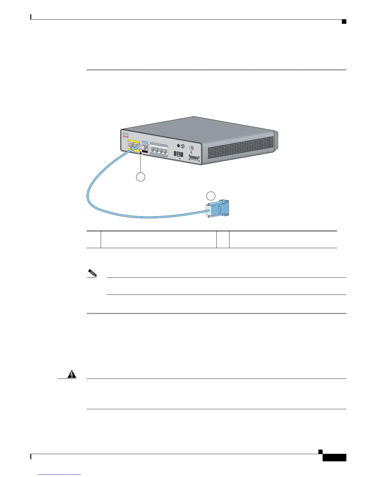
Step 1 Connect the RJ-45 end of a DB-9–to–RJ-45 serial cable to the RJ-45 Console Aux port on the voice
gateway.
Figure 3-7 shows the RJ-45 end of the serial cable connected to the Console Aux port on the
voice gateway.
Figure 3-7 Connecting a Terminal or PC to the Console Port
Step 2 Connect the DB-9 end of the RJ-45–to–DB-9 serial cable to the to the COM port on your laptop or PC.
Note Some laptops and personal computers do not have DB-9 serial port connectors and may require
a USB–to–serial port adapter.
Step 3 To communicate with the voice gateway, begin a terminal emulator application.
Connecting an FXS line
Use a standard straight-through RJ-11 modular telephone cable to connect a Foreign Exchange Service
(FXS) port to a telephone or fax machine.
Warning
This equipment contains a ring signal generator (ringer), which is a source of hazardous voltage. Do
not touch the RJ-11 (phone) port wires (conductors), the conductors of a cable connected to the RJ-11
port, or the associated circuit-board when the ringer is active. The ringer is activated by an incoming
call.
1 RJ-45 connector to the Console Aux port on
the voice gateway
2 DB-9 connector
VG204
1
2
V
D
C
S
A
CONSOLE
AUX
FastE
the
r
n
et
0/1
0
/0
FXS
0
/1
0/
20/3
0
/0
2
1
272270

 Loading...


