3-9
Catalyst 3560 Switch Hardware Installation Guide
OL-6337-07
Chapter 3 Switch Installation (8- and 12-Port Switches)
Installing the Switch
Step 4 Use a 0.144-inch (3.7 mm) or a #27 drill bit to drill a 1/2-inch (12.7 mm) hole in the three screw
template slots.
Step 5 Insert three screws in the slots on the screw template, and tighten until they touch the top of the screw
template.
Step 6 Remove the screw template from the desk or shelf.
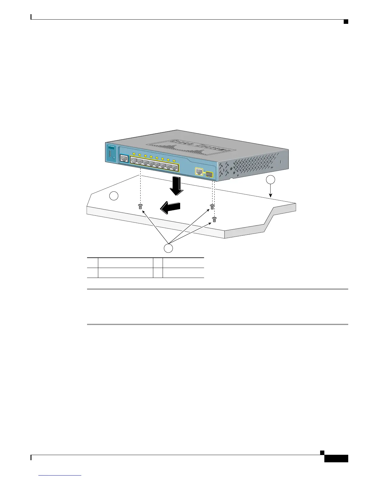
Step 7 Place the switch on the mounting screws, and slide it forward until it locks in place, as shown in
Figure 3-2.
Figure 3-2 Mounting the Switch on a Desk or Shelf With Mounting Screws
Under the Desk or Shelf Mounting
Step 1 Locate the screw template. The template helps to align the mounting screw holes and is a guide to make
sure the screws are installed under the desk or shelf with proper clearance.
Step 2 Position the screw template underneath the desk or shelf so that the two side-by-side slots face the front
of the desk or shelf, as shown in Figure 3-3. This ensures that the power cord faces the rear of the desk
or shelf after the switch is installed. Wait before you attach the screw template to the desk or shelf.
1 Slides on this way 3 Desk or shelf
2 Screws 4 Wall
3
2
1
1
CONSOLE
1x
2x
3x
4x
5x
6x
7x
8x
Catalyst 3560
S
ERIES
PoE-8
PoE
SPD
DP
LX
STAT
SYST
M
ODE

 Loading...


