Page 4 CI Man u al
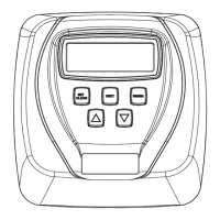
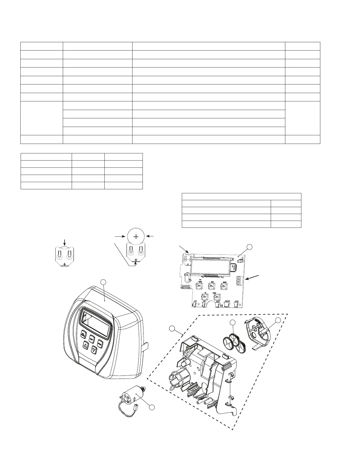
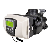
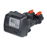
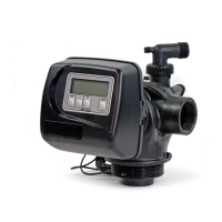
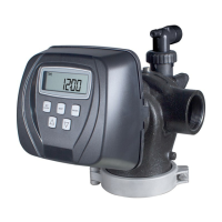
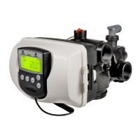
Front Cover and Drive Assembly
Drawing No. Order No. Description Quantity
1 V3175CI-01 WS1CI FRONT COVER ASSEMBLY 1
2 V3107-01 WS1 MOTOR 1
3 V3002-A WS1 DRIVE BRACKET ASY 1
4 V3108CI-06BOARD WS1 THRU 2 CI PCB XMEGA REPL 1
5 V3110 WS1 DRIVE REDUCING GEAR 12X36 3
6 V3109 WS1 DRIVE GEAR COVER 1
Not Shown
V3186-06 WS1 POWER SUPPLY US 15VDC HOCP
1
V3186EU-06 WS1 POWER SUPPLY EU 15VDC HOCP
V3186UK-06 WS1 POWER SUPPLY UK 15VDC HOCP
V3186-01 WS1 POWER CORD ONLY
Not Shown V3178 WS1 DRIVE BACKPLATE 1
1
2
5
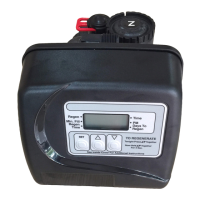
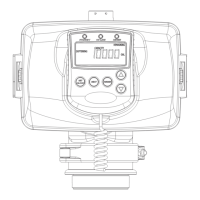
Battery Fully Seated
When replacing the battery, align
positives and push down to fully seat.
Power Supply U.S. International
Supply Voltage 100-120 VAC 100-240 VAC
Supply Frequency 50/60 Hz 50/60 Hz
Output Voltage 15 VDC 15 VDC
Output Current 500 mA 500 mA
Battery replacement is
3 volt lithium coin cell
type 2032.
Correct
Battery
Orientation
6
4
PC Board Relay
Terminal Block
Relay Driver Output Type – Dual Solid-State 12VDC “wet” contacts - N.O.
Relay Driver Output Capacity - 12VDC @100mA per relay output (total
current through both outputs not to exceed 200mA).
NOTE: Check for proper mounting dimensions on valve backplate prior to
mounting an external relay under control cover
Wiring for Correct On/Off Operation
PC Board Relay Terminal Block Relay
RLY 1 Coil -
+ COM Coil +
RLY 2 Coil -
3