Page -56- Clarke
®
Operator's Manual - FUSION 20 / 20T
Clarke
®
Fusion 20
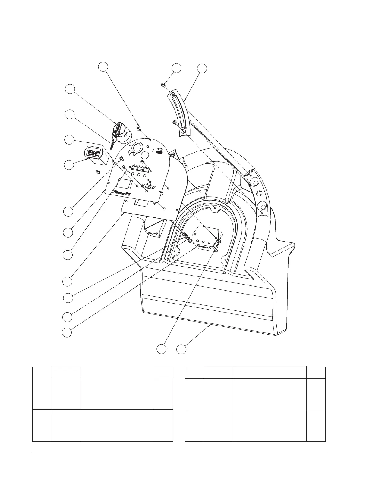
Handle Assembly Drawing and Parts List 2/08
Ref. Part No. Description Qty.
1 962957 Screw, 10-16 x 1/2 Self Tap 3
2 80104A Screw, 10-32 x 1/2 S.S. 4
3 11131A Switch, Control Handle Asm. 2
4 30826A Handle, Control 1
5 920065 Nut, 8-32 E.S.N.A. 2
6 41035A Meter, Battery/Low Voltage 1
7 980603 Washer, #10 Lock Ext. Tooth 2
8 920224 Nut, 10-32 HEx 2
Ref. Part No. Description Qty.
9 61920A Panel, Control 1
10 41036A LED, Battery Charger 1
11 71432A Label, Control Panel 1
12 962027 Screw, 8-32 x 1/2 P.H. 2
13 912226 Meter, Hour 12V DC 1
14 85383A Screw, 10-32 x 3/4 P.N. 1
15 40786S Spacer, Key Switch 1
16 40786A Swich, Key Hobbs 1
1
2
3
45
6
7
8
9
10
11
12
13
14
15
16
 Loading...