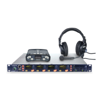
To select a mode, move the J1 jumper on the CPU rear card to one of two
positions. The J1 jumper is located on the inner-matrix side of the DB-25
connector.
For opto-isolated mode, fit the J1 jumper across pins 1 and 2.
For non-isolated mode, fit the J1 jumper across pins 2 and 3.
It is recommended that the connector is set to the fully opto-isolated mode.
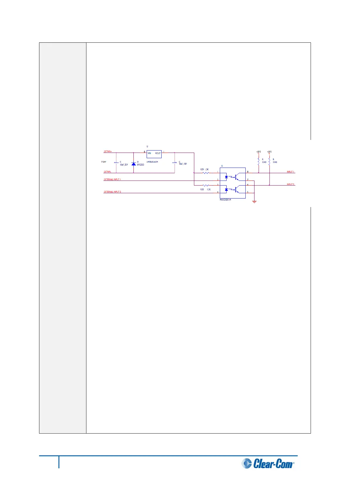
Opto-isolated mode
Figure 18: Opto-isolated mode
In this mode, a DC voltage of between 7 and 24 volts is required at the
EXTVIN+ pin with relation to the EXTVIN– pin. To cause an input to detect
an active signal, current must flow from the relevant input pin.
The external device should draw no current to cause an inactive input and
at least 5 mA to cause an active input. The opto-isolator drive line contains
a 1.5 kOhm resistor to limit the current through the opto-isolator. Therefore
the input pins can be connected directly to the EXTVIN– level to cause an
active input.
The voltage level at the external input pin should not be allowed to go below
EXTVIN– or above +6 V with respect to EXTVIN–.
Non-isolated mode
To cause an input to detect an active signal in non-isolated mode, the
current must flow from the relevant input pin.
The external device should draw no current to cause an inactive input and
at least 5 mA to cause an active input. The opto-isolator drive line contains
a 1.5 kOhm resistor to limit the current through the opto-isolator.
Therefore the input pins can be connected directly to a ground pin to cause
an active input.
The voltage level at the external input pin should not be allowed to go below
ground or above +6 V with respect to ground.
49
Eclipse HX-Median User Guide