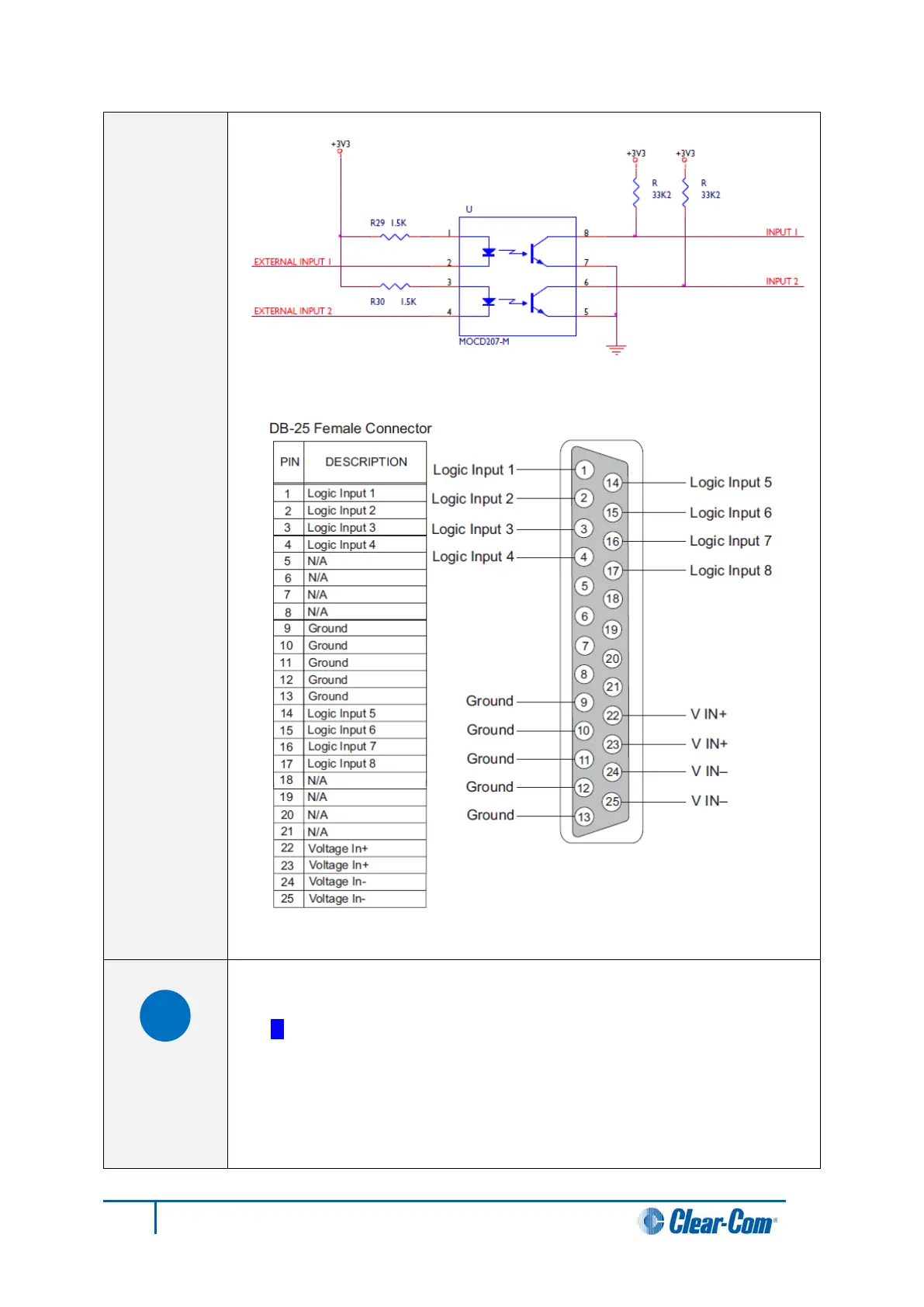
Figure 19: Non-isolated mode
Figure 20: Pin configuration of the General Inputs connector
Local Area Network connector (LAN1)
The LAN1 and LAN2 connectors have standard Ethernet pin assignments.
See G below for pin assignments.
The RJ-45 socket labeled LAN 1 connects a local area network (LAN) to the
CPU card through a standard Ethernet connection.
The green LED indicates the port is connected and the amber LED
indicates activity.
50
Eclipse HX-Median User Guide