Page 18 BB6100 Operating Manual
6. Use existing holes if they align with slots in the spider bearing supports.
Otherwise, drill and tap new holes or weld to work piece. If holes are to be drilled
and tapped, with the spider against the work, and mark their alignment.
7. Pull the bearing supports from the boring bar. Remove the boring bar from the
work piece.
8. If necessary, drill and tap suitable mounting holes in the end of the work piece to
align with slots in the spider bearing supports.
9. Mount one bearing support to the end of the work piece.
10. Slide the boring bar through the bearing support.
11. If the RDU is to be mounted between supports, mount it now.
12. Make sure the RDU shaft collars are on the drive hub. See Section 3.6 on page 24
for mounting information.
13. For mounting another end-mount bearing support, repeat steps #8 through #10. If
using an ID-mount bearing assembly, see Section 3.4 on page 19. CLIMAX
recommends no fewer than two support assemblies to obtain adequate machine
stability. The maximum recommended unsupported bar length is 5 feet (1.5 m).
See Section 3.2 on page 15.
14. Slide the boring bar through all bearing assemblies and position axially. Use an
additional bar clamp as necessary when the bar is in a vertical orientation (see
Section 3.1 on page 15).
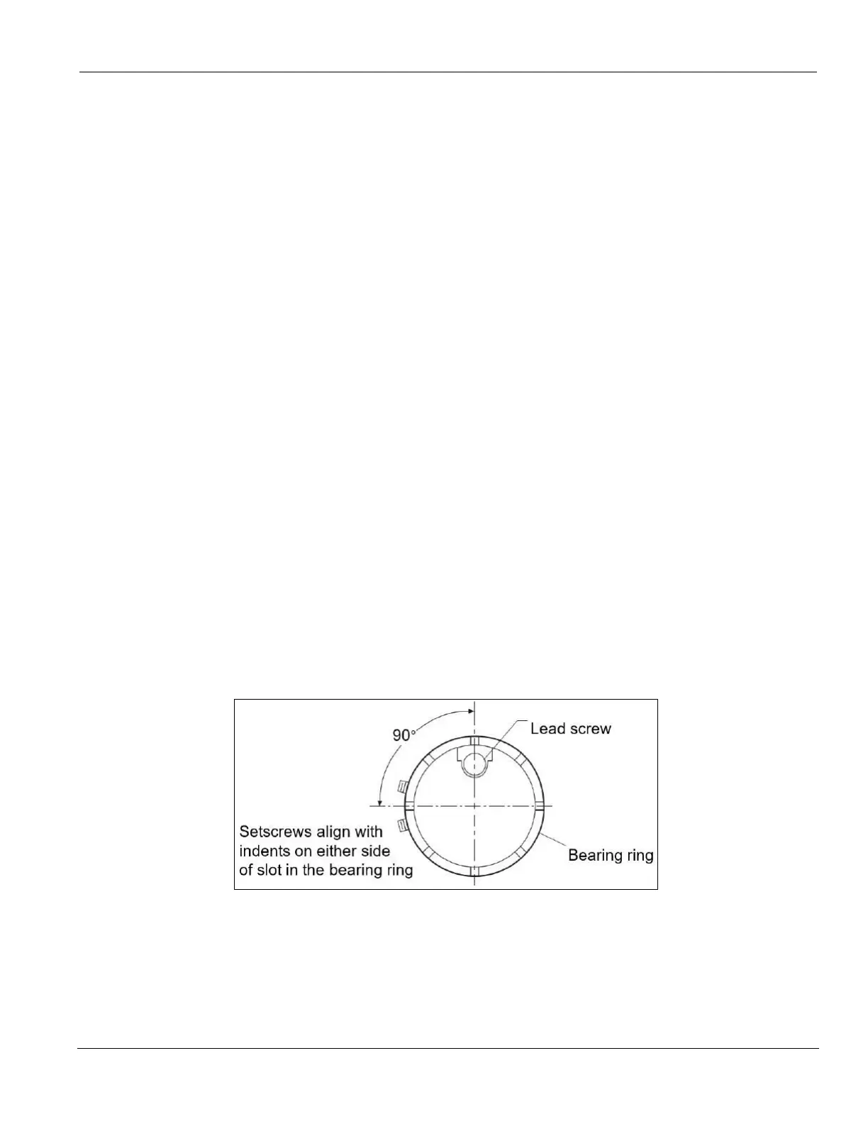
15. Do the following to clamp the bearing support onto the bar:
a. Align two setscrews in the bearing with the indentation in the bearing
ring.
b. Adjust the bearing ring (and screws) so it is 90° to the lead screw in the
bar.
c. Tighten the setscrews evenly until the bar is held firmly.
FIGURE 1. LEAD SCREW (TOP) AND BEARING RING (RIGHT)
16. Do the following to precisely align the boring bar:
a. Use a dial indicator and four adjusting screws to center the boring bar in
the bore.
b. Tighten the four locking screws.