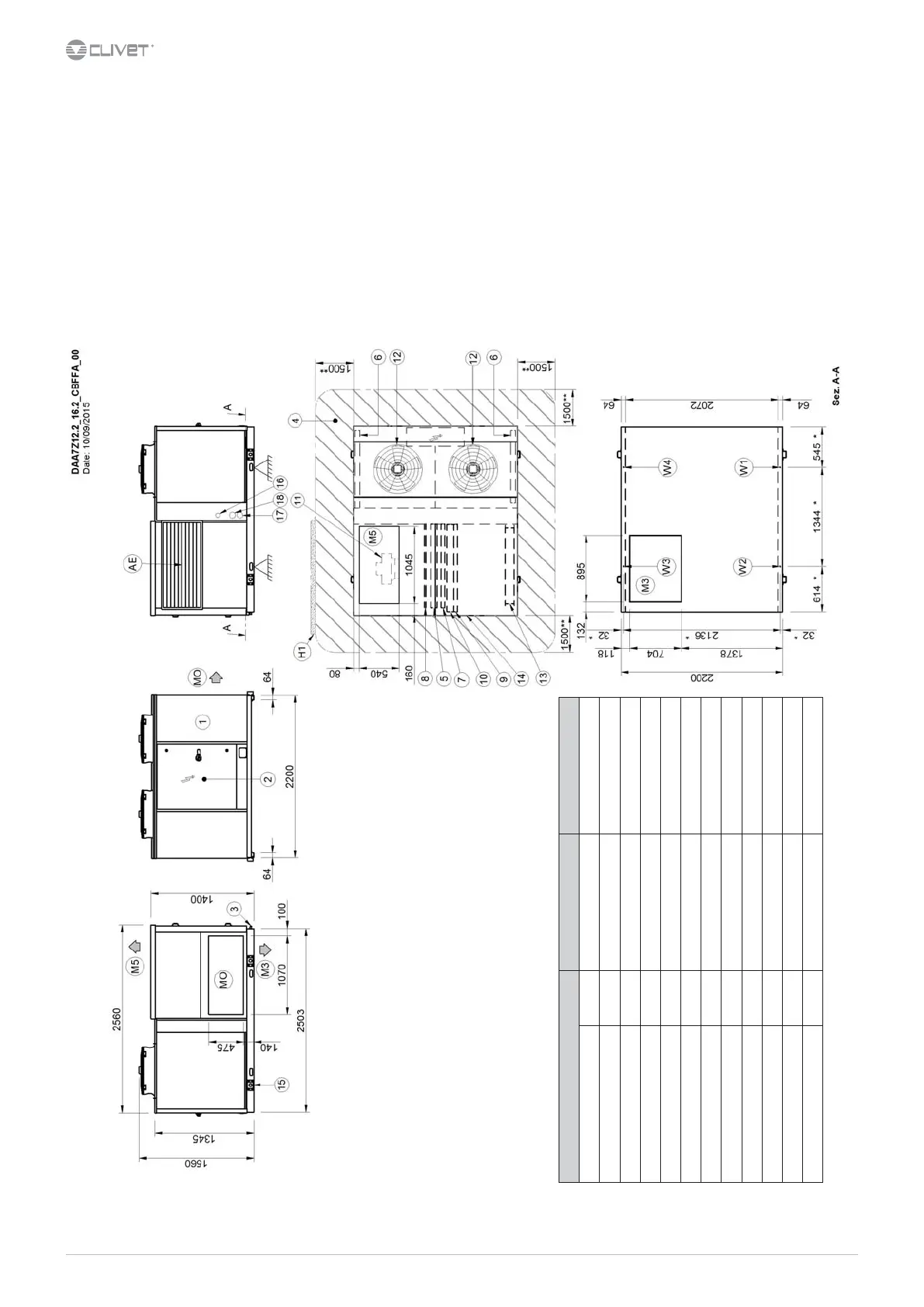
Size 15.2 - 18.2 - CCK and CCKP conguration
1. Compressor compartment
2. Electrical panel
3. Condensate drain
4. Functional clearances
5. Internal exchanger
6. External exchanger
7. H2O heating coil / Electric heaters (Optional)
8. Re-heating coil (Optional)
9. G4 air lters (Standard)
10. F7 bag lters / H10 electronic air lters (Optional)
11. Electric fan (Supply - return)
12. External electric fan
13. Outdoor air damper
14. Access for inspection of coils, lters, heating elements
15. Lifting brackets (removable)
16. Humidier connections
17. H2O heating coil input Ø 1”1/4
18. H2O heating coil output Ø 1”1/4
19. Exhaust electric fan
20. Exhaust air recovery coil (CCKP version)
(RO) Horizontal air return
(R3) FLoor air inlet (optional)
(M0) Horizontal air supply
(M3) Downward airow (Optional)
(M5) Upward airow (Optional)
(ML) Lateral supply (Optional)
(AE) Outdoor air return
(H1) Wall with same height as unit on a maximum of three sides
(**) Suggested clearance
(*) Vibration mounts position
Size 15.2 15.2 18.2 18.2
Conguration CCK CCKP CCK CCKP
W1 supporting point kg 209 277 213 282
W2 Supporting point kg 286 223 293 228
W3 Supporting point kg 281 258 287 264
W4 Supporting point kg 239 287 243 292
Operating weight kg 1015 1045 1036 1066
Shipping weight kg 1015 1045 1036 1066
The presence of optional accessories may result in a substantial variation of the weights shown in the table.
 Loading...