LAYOUT OF PCB BOARDS
48
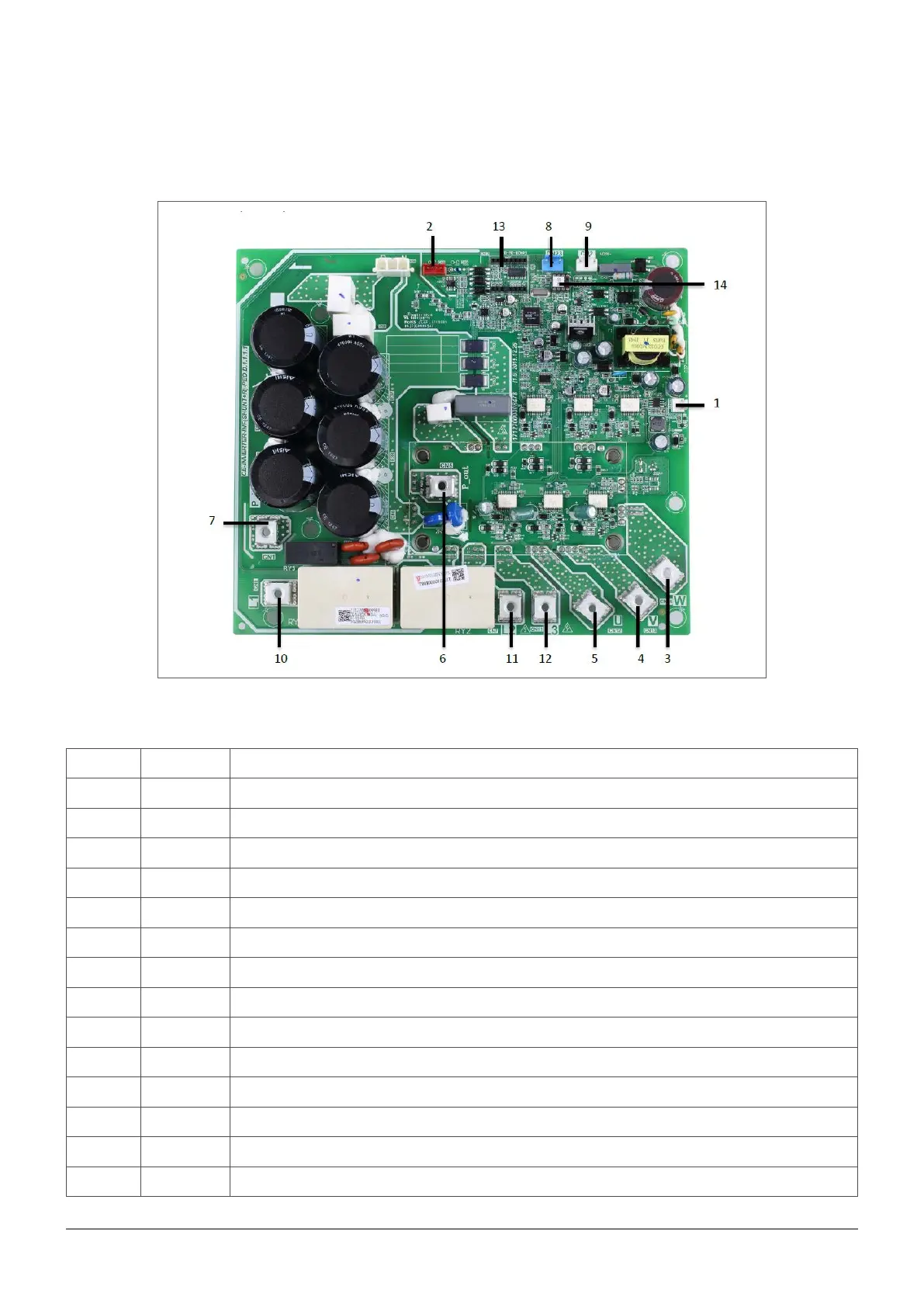
6.10 Inverter module - 9.1. - 10.1 - 12.1 - 14.1
Rif Sign Description
1 CN20 Output port for +15V
2 CN8 Port for communication with PCB B
3 W Compressor connection W
4 U Compressor connection U
5 V Compressor connection V
6 - Input port P_out for IPM module
7 - Input port P_in for IPM module
8 CN23 Input port for high pressure switch
9 CN2 Power supply for switching power output
10 L1’ Power filtering L1
11 L2’ Power filtering L2
12 L3’ Power filtering L3
13 - PED board
14 IC25 EEPROM
 Loading...