95
TROUBLESHOOTING
L0 Troubleshooting
Situation 1: L0 error is displayed immediately after the unit is switched on
L0
↓
Communication wire between the main control
board of the refrigerant system for the inverter
module (4-pin) is not connected properly (1)
YES →
Ensure the communication wire is connected
properly
NO
↓
Inverter module is damaged (2)
YES
→
Replace the inverter module 4
NO
↓
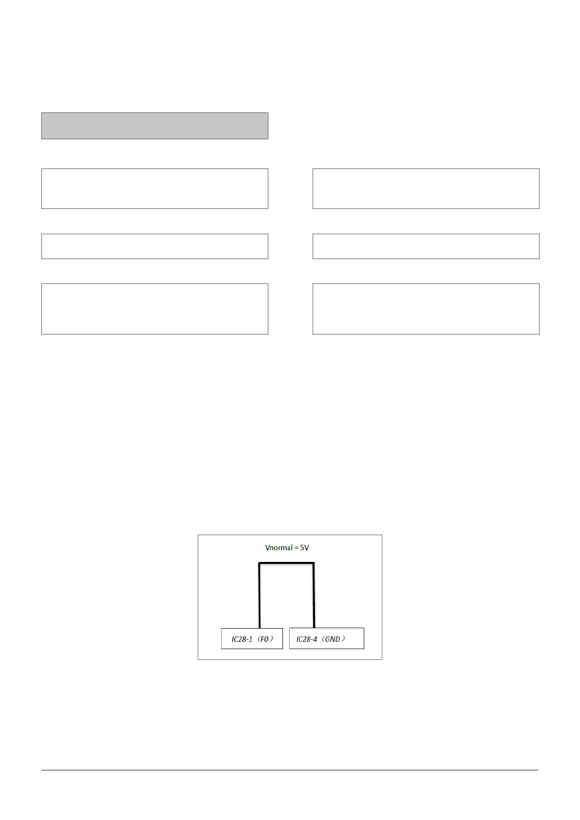
The voltage between pins F0 and GND of the
communication port for connection to the inverter
module on the refrigerant circuit board is too low
(3)
YES →
Replace the inverter module 4
Notes:
1 The communication port between the main control board of the refrigerant system and the inverter module
of the refrigerant system is: port CN36 on the main control board of the refrigerant system and port CN8 on
the inverter module of the refrigerant system.
2 Measure the resistance between each of U, V and W terminal and each P and N terminal on the inverter
module. All the resistances should be infinite. If any of them are not infinite, the inverter module is damaged
and should be replaced.
3 The normal voltage between F0 and GND is 5V.
4 When replacing an inverter module, a layer of thermally conductive silica gel should be painted on the IPM
module, IGBT, diode, bridge rectifier (on the reverse side of the inverter module PCB).
Voltage F0 and GND on IC28-1F0, IC28-4 GND
 Loading...