MAN.219 Rev.8 ENG - Use and maintenance manual S19N page 14 of 71
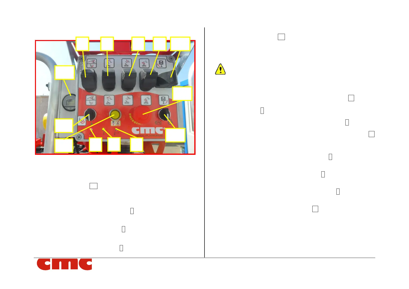
3.2.1 Platform (operating) control station
Picture 5: platform (operating) control station.
The platform (operating) control station (Picture 5) is located inside the
basket, and it is formed by:
• engine selector MS (Picture 5): turning the knob to the right the
endothermic engine starts; turning it to the left the electric engine is
activated.
• electrical power supply indicator 3 (Picture 5): when the green
led is on, the PLE is electrically powered;
• moment limiter early warning 4 (Picture 5): this yellow led turns
on when the outreach reaches 80% of the maximum allowed;
• moment limiter lock warning 5 (Picture 5): this red light turns on
when the outreach reaches the maximum threshold;
• emergency button EB (Picture 5): this red and mushroom-
shaped switch blocks the machine by removing the power supply
to the control circuits. It has priority over any other command: it
makes possible only the manual emergency lowering of the ma-
chine on the ground.
The emergency button has an auto-detent mechanical locking
system; therefore, it is necessary to unlock the button turning it
clockwise to reset its operability.
• dead man switch for levelling operations consent 11 (Pic-
ture 5): it is necessary to keep this button to the left together
with the lever 6 (Picture 5);
• joystick lever for jib movements/basket levelling 6 (Picture 5):
it carries out the levelling (downward – internal leveling, upward –
external leveling), if moved together with the dead man switch 11
(Picture 8). Alone, it also allows the jib lifting upward and the jib
lowering downward.
• joystick lever for boom extension/re-entry 7 (Picture 5): upward
for its extension and downward for its re-entry.
• joystick lever for boom lifting/lowering 8 (Picture 5): upward for
its lifting and downward for its lowering.
• joystick lever for pantograph lifting/lowering 9 (Picture 5): up-
ward for its lifting and downward for its lowering.
• joystick lever for turret rotation 10 (Picture 5): upward for
clockwise rotation and downward for counterclockwise rotation.