MAN.219 Rev.8 ENG - Use and maintenance manual S19N page 15 of 71
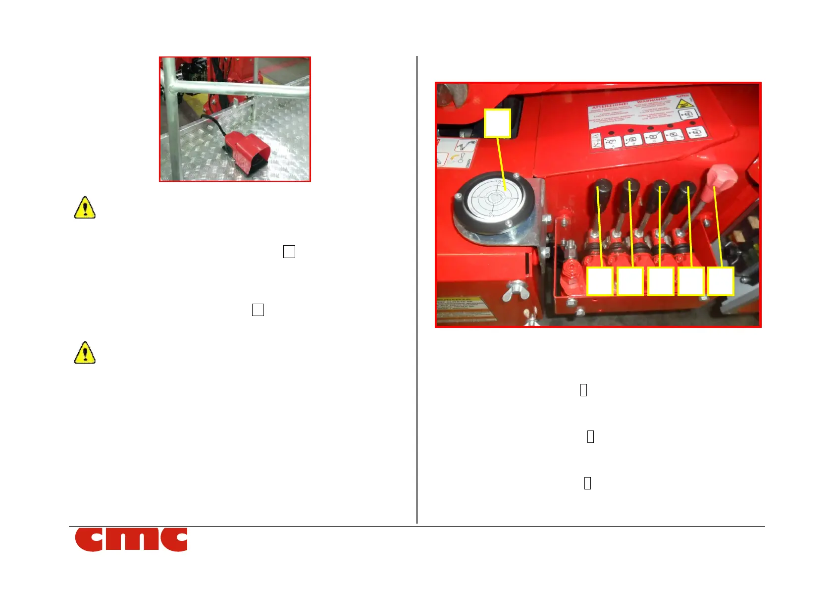
Picture 6: dead man pedal (*optional).
It is necessary to keep the pedal (Picture 6) pressed simultane-
ously with the lever of the selected maneuver, if supplied.
• dead man anti-crash bypass button 12 (Picture 5): during the
closing operations of the machine, if the machine stops because of
crash danger, it is possible to go on the operations pushing this
button with the maneuver joysticks.
• battery charge level indicator 13 (Picture 5 - *optional): it is a
digital display that shows the state of batteries charge in percent-
age.
Every time the charge state of the batteries is under 10%, all
work operations are blocked.
• 12 V socket.
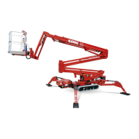
3.2.2 Outriggers control station
Picture 7: stabilizers control station.
The outriggers control station (Picture 7) is placed on the chassis and it is
composed by:
o left rear stabilizer lever 1 (Picture 7)
- pushing the lever forward, the stabilizer lowers.
- pushing the lever backward, the stabilizer withdraws.
o right rear stabilizer lever 2 (Picture 7)
- pushing the lever forward, the stabilizer lowers.
- pushing the lever backward, the stabilizer withdraws.
o left front stabilizer lever 3 (Picture 7)
- pushing the lever forward, the stabilizer lowers.
- pushing the lever backwards, the stabilizer withdraws.