MAN.219 Rev.8 ENG - Use and maintenance manual S19N page 16 of 71
o right front stabilizer lever 4 (Picture 7)
- pushing the lever forward, the stabilizer lowers.
- pushing the lever backwards, the stabilizer withdraws.
o crawler’s extraction/retraction red lever 5 (Picture 7) (*optional)
o bubble level L (Picture 7): it allows to control that the chassis in-
clination remains within the maximum value allowed by the manu-
facturer, that is equal to 1°.
3.2.3 Travel control station
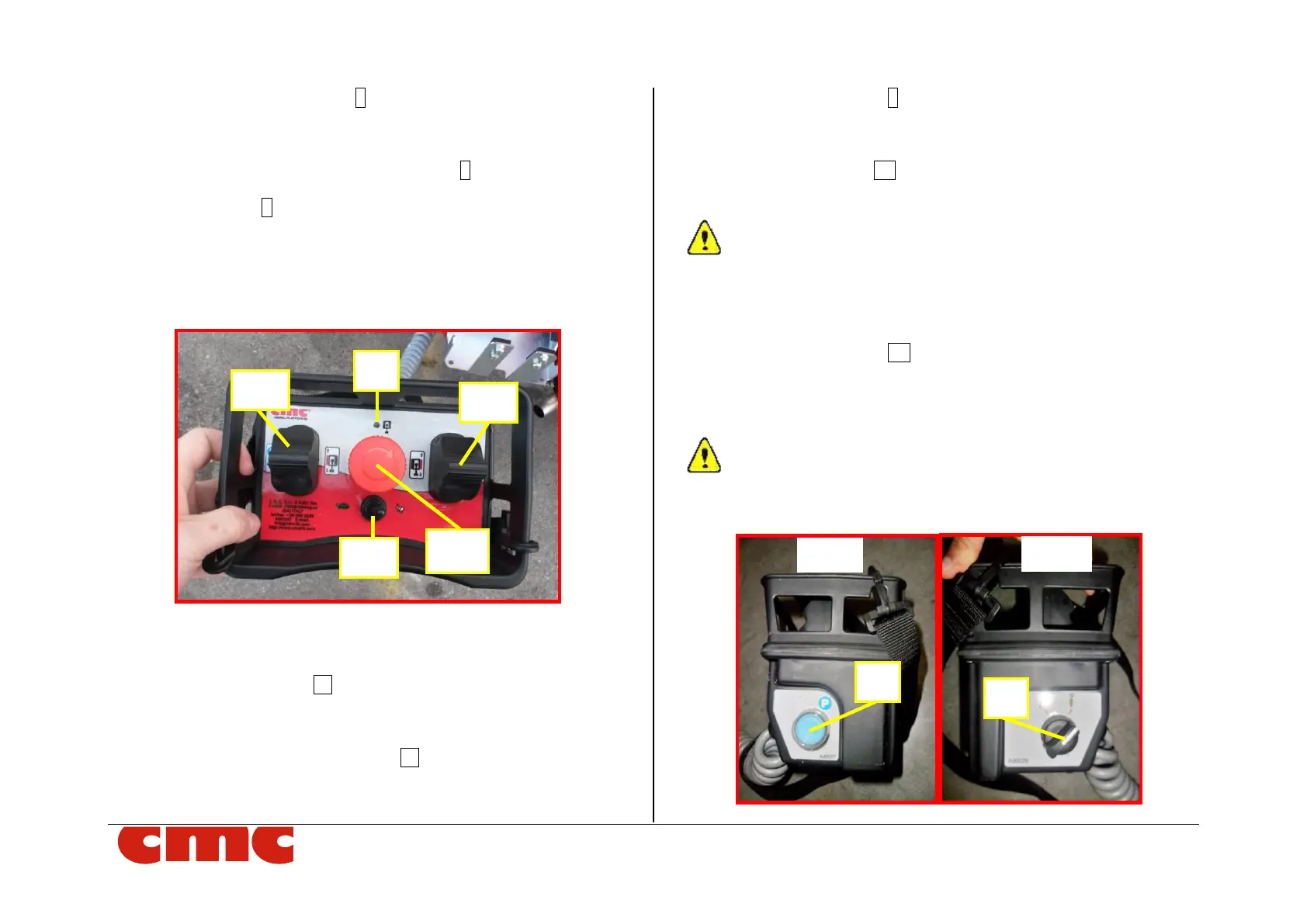
Picture 8: MEWP travel (wired remote control) station.
The wired remote control station has the following commands:
o left crawler joystick J1 (Picture 8)
- pushing it upward, the left crawler goes forward;
- pushing it downward, the left crawler goes backward;
o right crawler activation buttons J2 (Picture 8)
- pushing it upward, the left crawler goes forward;
- pushing it downward, the left crawler goes backward;
o travel consent light 6 (Picture 8): this orange light, when turned
on, indicates the consent to the travel operations (with machine
closed).
o travel speed lever SS (Picture 8): moving it to the left, the “turtle”
mode (minimum speed) is activated; moving it to the right, the
“hare” mode (maximum speed).
The tracks should remain extended to maximum width for improved stability
and increased ground clearance when traveling with the MEWP (*optional). The
exception is when traveling through a narrow passage, the tracks may need to be
retracted to decrease the overall width of the MEWP. It is recommended that the
tracks be extended again as soon as possible.
o emergency button EB (Picture 8): this red and mushroom-
shaped switch blocks the machine by removing the power supply
to the control circuits. It has priority over any other command: it
makes possible only the manual emergency lowering of the ma-
chine on the ground.
The emergency button has an auto-detent mechanical locking
system; therefore, it is necessary to unlock the button turning it
clockwise to reset its operability.
Picture 9: left and right side of the wired remote control.