MAN.241 Rev.5 ENG - Use and maintenance manual S23 page 15 of 127
2.3.1 Frame
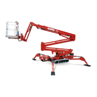
The frame 1 (Picture 3) is a steel structure having a
quality appropriate in order to distribute the weight of
the equipment when the MEWP is in driving position.
The frame features 4 hydraulic jacks for stabilization.
The base for the support slewing ring is on the frame
and through the rotation unit allows the tilting of the
equipment.
2.3.2 Turret
The turret 5 (Picture 3), made of quality steel, is fixed
to the bearing (slewing ring). The rotation of the su-
perstructure is allowed by a hydraulic power with
brake normally closed, constrained to the turret.
2.3.3 Pantograph
The pantograph 6 (Picture 3) consists of two pairs of
parallel booms (pantograph upper crank and panto-
graph lower crank) and of the pantograph connecting
rod 7 (Picture 3). The booms (tubular with rectangu-
lar section, bended and electro-welded) and the con-
necting rod are made with high quality steel sheets.
The movement of the pantograph (lifting and lower-
ing the pantograph) is obtained thanks to the hydrau-
lic cylinder for lifting the pantograph 12 (Picture
3).This cylinder is fastened to the turret (barrel side)
and to the upper pantograph crank (rod side) and is
equipped with double-acting balancing valve.
The double pantograph has an operating field from
0° to about +65° (with respect to the horizontal).
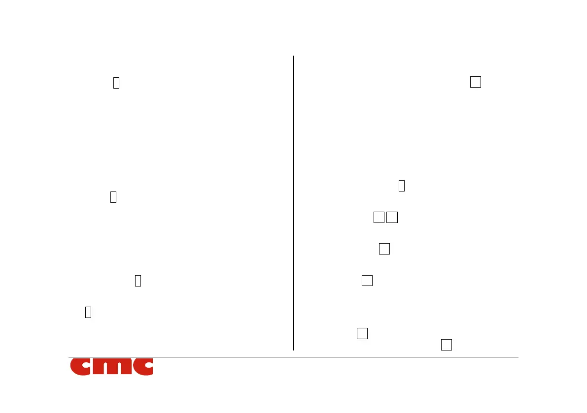
2.3.4 Telescopic boom
The telescopic boom 8 (Picture 3) is hinged to the
turret. The telescopic boom is made up of three ele-
ments: a fixed boom hinged to the turret and two ex-
tensible booms 10 11 (Picture 3).
The extraction movement (or return) of the telescopic
boom is obtained by moving the "telescopic boom ex-
traction cylinder" 13 (Picture 3).
The lifting (or lowering) movement of the telescopic
boom is obtained by moving the "telescopic boom lift-
ing cylinder" 14 (Picture 3).
2.3.5 Basket
The basket 16 (Picture 3) is connected to the second
extensible boom through the jib 15 (Picture 3). It is