MAN.243 Rev.5 ENG - Use and maintenance manual S28 page 18 of 138
3 Command stations
3.1 Machine switching on/off
station
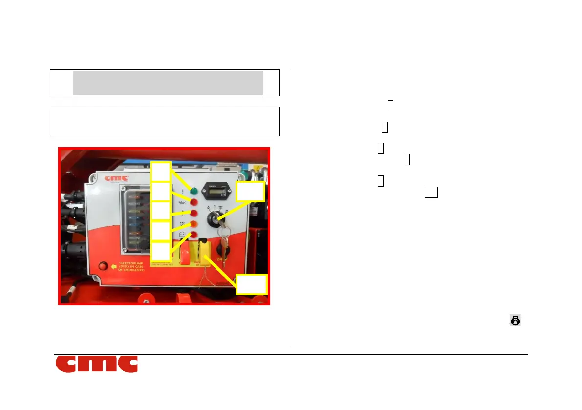
Picture 4: engine switch on/off station.
The main electric box (Picture 4), located on the right
side of the frame, provide:
• the IK ignition key: through it, it is possible to turn
on the electric system and start the endothermic
engine;
• the green light 5 indicating system power supply: it
is on when the AM key is in position 1;
• the red light 4 which signals low pressure to the
engine oil;
• the red light 3 which monitors coolant level;
• the orange light 2 indicating the spark plugs
working;
• the red light 1 which signals an alternator failure;
• the emergency bypass BP under the yellow cap
(see par.4.6.2);
• the activation lever of remote connection under the
red cap (see par.8.16.1);
• the hourcounter;
• the 24 V socket;
• the red activation button of electropump*.
3.1.1 Ignition of the endothermic engine
In order to start the endothermic engine, turn the IK
ignition key all the way to the right up to the symbol .