MAN.243 Rev.5 ENG - Use and maintenance manual S28 page 35 of 138
By pressing the down arrow key, the Chassis C1 and C2
screens (Picture 22) are displayed, highlighting the
various system inputs:
- with the green leds on, the work areas in which the
outriggers are open (ON GROUND NO - normally
open on the ground);
- with the green leds off, the unused work areas
where the outriggers are not open (ON GROUND
NC - normally closed on the ground).
- emergency button of the outriggers control station;
- use of diesel engine;
- stabilizing pins inserted;
- use of electric engine;
- boom 1 resting on a support;
- monitored electro valve of the outriggers.
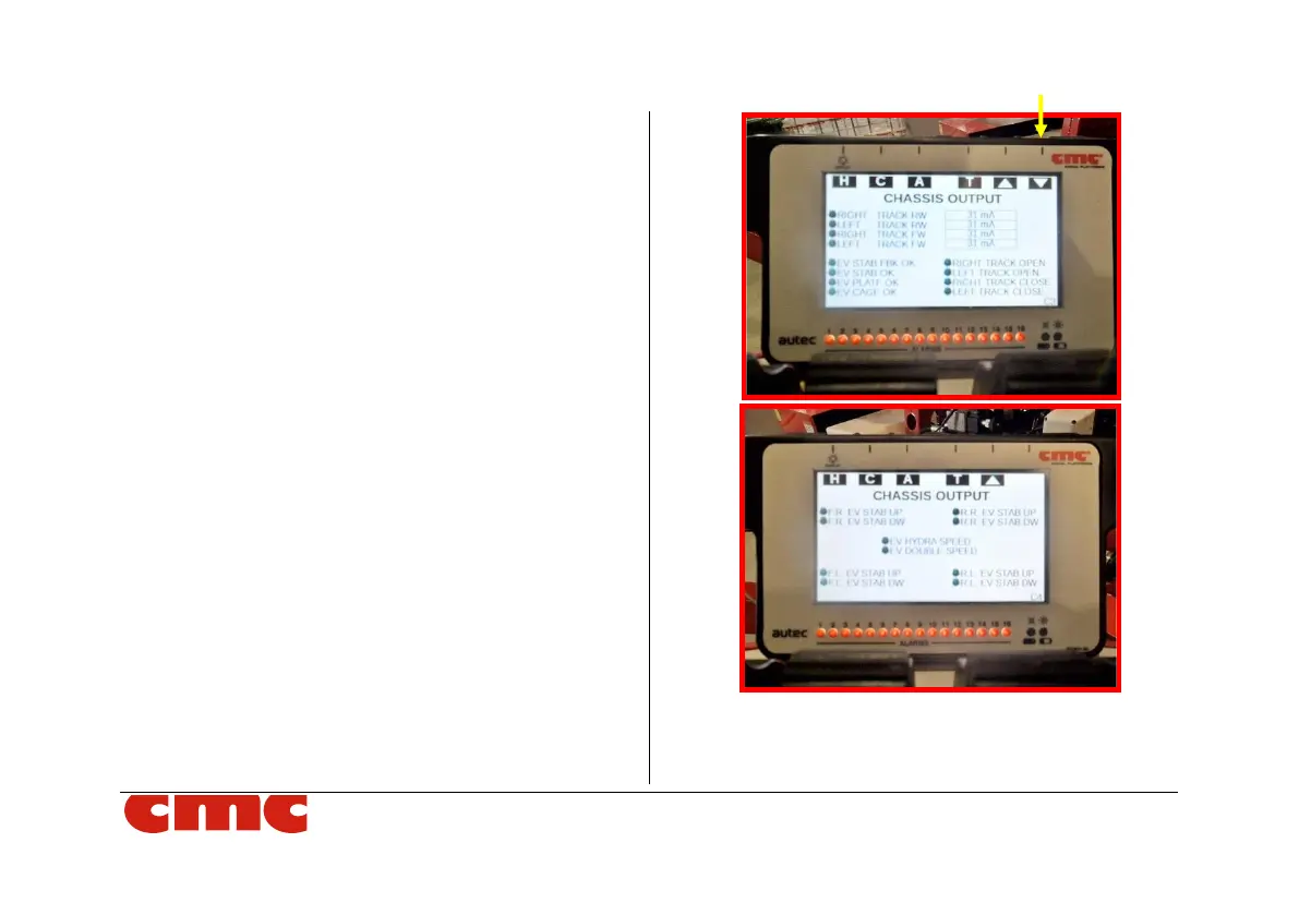
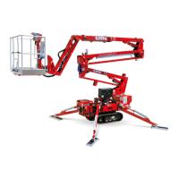
Picture 23: Chassis C3-C4 screens.
In the screens C3 and C4 (Picture 23), related to the
"Chassis output", you can monitor: