MAN.243 Rev.5 ENG - Use and maintenance manual S28 page 34 of 138
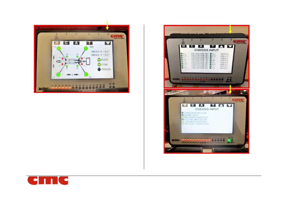
Picture 21: Chassis screen.
Pressing the second key from the left C, you access the
"Chassis" screen (Picture 21). In the C0 screen, a map
of machine leds indicates the working areas A1-A2
selected for each outrigger. As soon as stabilization is
performed (par. 4.4.2), also the leds indicating the
outriggers FR (front right) - FL (front left) - RR (rear right)
- RL (rear left) will change from red to green; the consent
light PLATF for use of the aerial part turn on,
simultaneously with the turning off of the consent light
TRACKS for use of tracks.
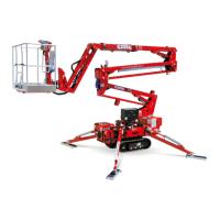
Picture 22: Chassis C1-C2 screens.