OPERATING MANUAL
800.749.2761 www.coachcomm.com
10
Press Box Rack Unit Overview
The Press Box Rack Unit houses the system’s Wired Interface, Control Unit, and antenna connection panel. See page 11
of this manual for more information about the Wired Interface, and see page 13 for more information about the Control
Unit.
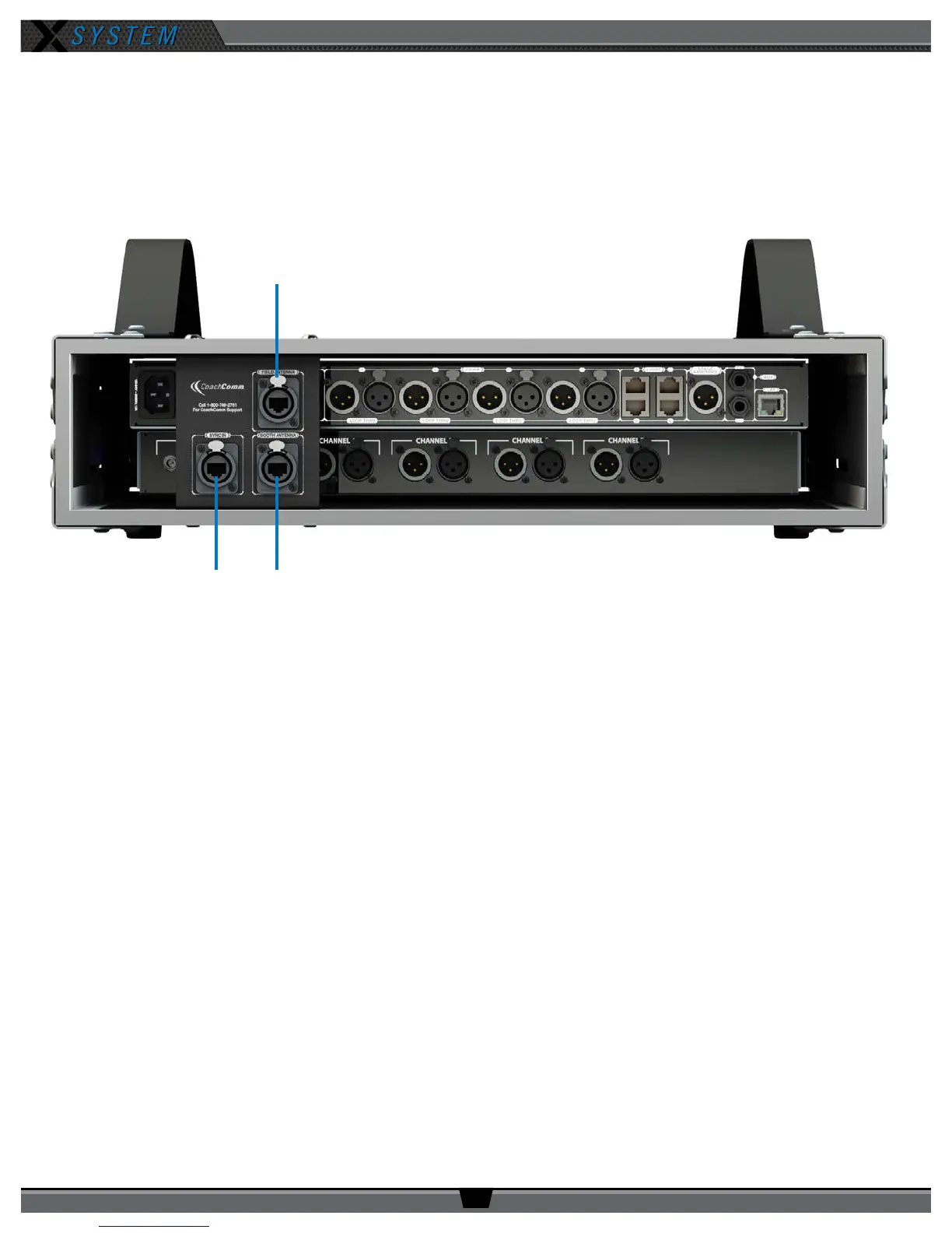
Press Box Rack Unit Rear
A. FIELD ANTENNA Port – Connection for the Cat 5 cable from the eld antenna(s).
B. SYNC IN Port – Allows the system to be synchronized with another X-System. Sync is recommended when more
than two unsynchronized X-System Antennas are operating in close proximity to one another.
C. BOOTH ANTENNA Port – Connection for the Cat 5 cable from a booth antenna.
Note: Audio and power cables are not pictured in Figure 10.
Find more information about connecting antennas to the system on pages 5 and 26 of this manual.
A
Cables not shown.
Figure 10: Press Box Rack Unit Rear View