OPERATING MANUAL
800.749.2761 www.coachcomm.com
17
Radio Transceiver/Antenna (XRT-ANT-900)
The X-System Radio Transceiver (RT) serves as a point of contact for Radio Packs on X-Net. It should be positioned as high
as possible to provide better and more expanded coverage. An antenna is attached to the front of the RT, and together,
the two devices are known as the “Antenna” throughout other sections of this manual. More information about mounting
Antennas is provided on page 26.
Six Radio Packs may be connected per Antenna.
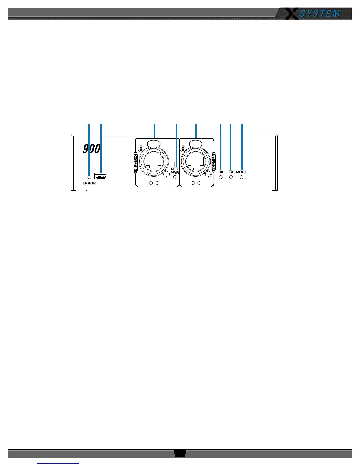
Radio Transceiver Bottom
A. ERROR LED – Indicates the device’s error status.
B. USB Micro B Connection – For connectivity to a PC when performing device rmware updates.
C. X-NET IN Port (RJ-45) and Status LEDs – The Antenna’s X-NET IN ports allow it to connect to any available
X-Net port or RT LOOP port on other devices, adding the RT to a proprietary network where all devices are part of
a system conguration that shares data, timing synchronization, and audio. Each RT has an X-NET IN port (RJ-45)
and an RT LOOP port (RJ-45, which allows RTs to be daisy-chained to one another).
D. Network Power (NET PWR) LED – On when network power is powering the device via connection to the CU.
E. RT LOOP Port and Status LEDs – The RT LOOP port allows you to connect multiple RTs together in a “daisy
chain.”
F. RX LED – Green LED—On when the Antenna is receiving transmissions from Radio Packs. This LED will blink
briey when a Radio Pack rst logs in to the Antenna and then return to normal operation.
G. TX LED – Green LED—On (blinking rapidly) when the Antenna is transmitting properly.
H. MODE LED – Green LED—On when set to Normal Mode.
Figure 19: Antenna Bottom View
A B C D E F G H