OPERATING MANUAL
800.749.2761 www.coachcomm.com
14
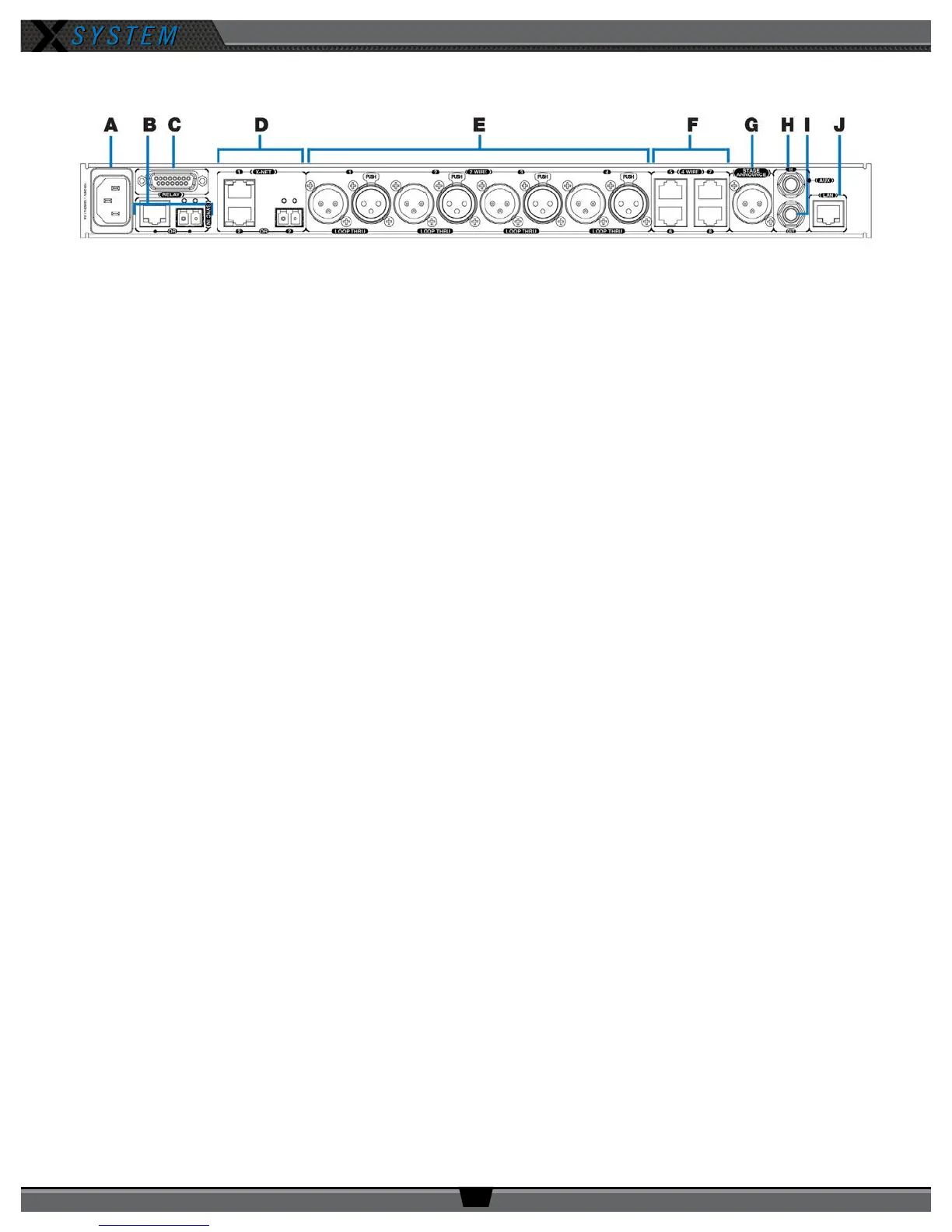
Control Unit Rear
A. AC Power Connection – 100–240V, 50/60 Hz 0.8A
B. SYNC IN Port (RJ-45 or Fiber) – Allows the system to be synchronized with another X-System. Sync is
recommended when more than two unsynchronized X-System Antennas are operating in close proximity to one
another.
C. RELAY Connection – Not currently used with X-System operation
D. X-Net Ports (RJ-45 or Fiber) – The X-Net ports allow the Control Unit to connect to other X-System devices,
such as Antennas, forming a proprietary network design where all devices are part of a system conguration that
shares data, timing synchronization, and audio.
E. 2 WIRE Intercom Port (x 4) –The Intercom conference ports (1, 2, 3, and 4) connect the Control Unit to channels
A/B and C/D of the Wired Interface.
F. 4 WIRE Intercom Port (x 4) – Not currently used with X-System operation
G. STAGE ANNOUNCE (SA) – Not currently used with X-System operation
H. Auxiliary Audio Input (AUX IN) – Not currently used with X-System operation
I. Auxiliary Audio Output (AUX OUT) – Not currently used with X-System operation
J. Local Area Network (LAN) Port – The LAN port allows the Control Unit to be connected to a PC and X-Ware. See
the “Connecting X-Ware to Your CU” section on page 32 of this manual for more LAN connection information.
Figure 16: XCU-44 Rear View