DIGIMINI AMERICAS REPEATERS
PRODUCT DESCRIPTION AND USER’S MANUAL
Cobham Wireless – Coverage Date: 6-Jul-17 www.cobham.com/wireless
Document number: 00031UM Rev. 6.3
Page |1-4
1.6 DIGImini Interfaces
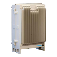
The DIGImini is supplied in two physical configurations:
• Single unit supporting (one or) two bands;
• Two cascaded units supporting up to four bands.
Power supplies
dedicated to each unit
are connected externally. An optional DMCU supporting an external
modem is also connected externally, where a single DMCU can serve two cascaded units.
The interfaces are located on the
front
and on the
side
panels.
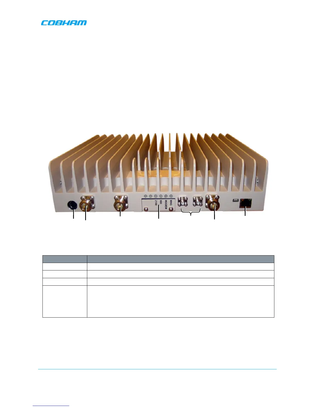
1.6.1 Front Panel Interfaces
The image below shows the unit (the wallmount bracket is not shown).
Figure
1-2: DIGImini Dual-Band Front Panel
The following table provides a description of the front panel connectors.
Port Description
MOBILE Service antenna connections.
BASE Donor antenna connections.
DC Power (12V) Circular, 4-PIN.
RJ 45 Used for setup.
Ethernet port can also be connected to the network or used to connect to an
external modem.
ATTENTION!! Do not connect to the network unless you have purchased
either the DMCU or the external modem support license file.
*Not in use. Termination is NOT required.