DIGIMINI AMERICAS REPEATERS
PRODUCT DESCRIPTION AND USER’S MANUAL
Cobham Wireless – Coverage Date: 6-Jul-17 www.cobham.com/wireless
Document number: 00031UM Rev. 6.3
Page |1-5
The following table provides a description of the front panel LED indicators (see 6.2.2 for more info).
LED Description
Band specific
LED
(e.g. 850, 1900, etc)
Downlink path status and RSSI indication:
MNG Relevant only if connected to DMCU:
CCD Operation status
MODEM Relevant only if connected to DMCU:
DMCU Modem operation status
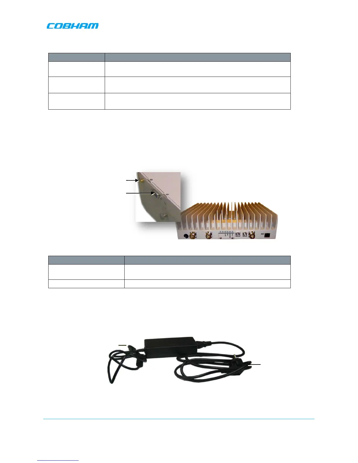
1.6.2 Side Panel Interfaces
The DIGImini side panel supports the DMCU interfaces and the side bolts used for hanging the unit on the
wall bracket. For DMCU interfaces descriptions refer to the DMCU User Manual.
Figure 1-3. DIGImini Side Panel
Side Connector Description
Modem DMCU Modem Antenna connection - relevant for installation with
a DMCU.
RS485 RS485 connection to DMCU option.
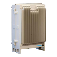
1.6.3 DIGImini Power Supply
The power supply requires assembly only during an upgrade procedure from a dual-band to a triple-band or
quad-band solutions in which two DIGImini units are cascaded. Otherwise, it is preassembled.
Figure 1-4: Repeater Power Supply