DIGIMINI AMERICAS REPEATERS
PRODUCT DESCRIPTION AND USER’S MANUAL
Cobham Wireless – Coverage Date: 6-Jul-17 www.cobham.com/wireless
Document number: 00031UM Rev. 6.3
Page |4-2
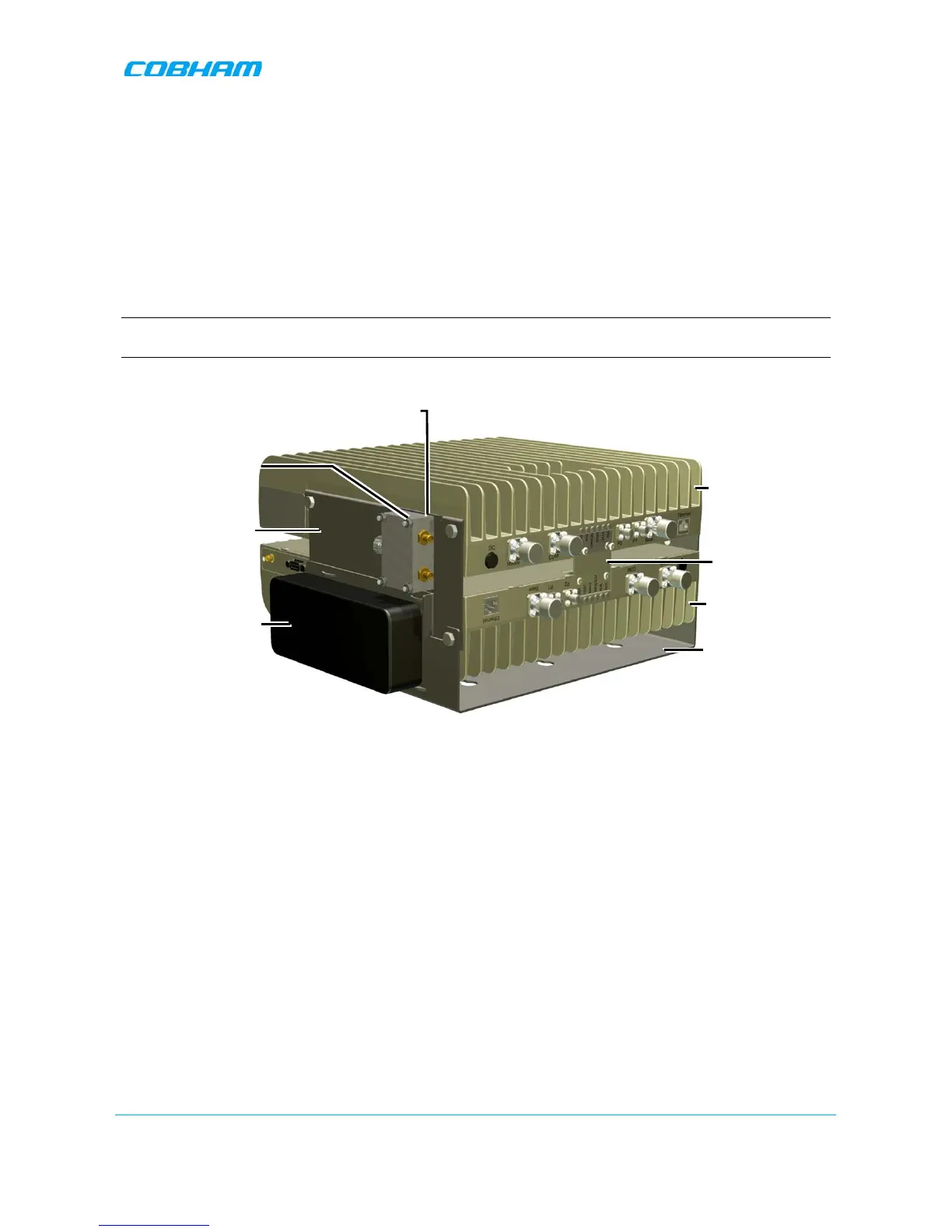
4.2 View of the Dual Unit Installation
The following figure illustrates the Quad-band DIGI-mini assembly.
The following figure illustrates the Triple/Quad-band DIGI-mini assembly.
Note the following:
• The Tri/Quad-band assembly supports
two RF combiners
, mounted on each side bracket.
• The front panel LED interfaces are interconnected and covered with a common tab.
NOTE: Illustration below shows a bottom view of the mounted Quad-band assembly (connectors face down
when the assembly is wall mounted).
Figure 4-1: Cascaded DIGImini Tri/Quad-band
4.3 Required Tools and Materials
The following is required in order to install the Repeater:
• Standard professional tool box
• A computer (i.e. laptop for running the setup) – refer to the single/dual band user manual for setup and
commissioning procedure.
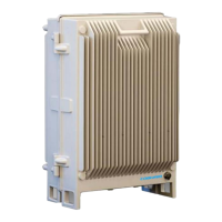
DIGImini Unit