Description of the system components
98-145510-E Chapter 2: Introduction 2-5
2.2.2 RF assembly
The RF assembly varies depending on the antenna type. The following pages show the RF
assemblies for EXPLORER 8100 Ku-Band, EXPLORER 8120 Ku-Band and EXPLORER 8100 Ka-
Band.
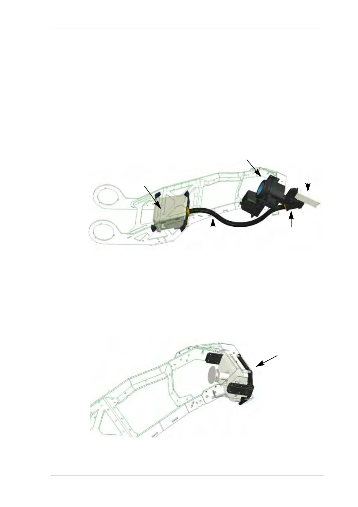
Ku-Band RF assembly
The Ku version features a distributed RF system with a Block Up Converter (BUC) placed in
the middle of the Feed support structure, connected to the Feed (Ortho Mode Transducer
(OMT)/Low Noise Blockdown converter (LNB)) via a Flexible Wave Guide (FWG). A motor
driven Polarizer is present.
The location of the RF components are the same on the EXPLORER 8120 as on the
EXPLORER 8100 shown above.
Ka-Band RF assembly
In the Ka Eutelsat/Viasat version, the components in the RF assembly are integrated in a
monolithic Transmit and Receive Integrated Assembly (eTRIA) unit, placed at the end of
the Feed arm. For specifications on the eTRIA, see ViaSat eTRIA on page A-11.
Figure 5: Components of the EXPLORER 8100 Ku-Band RF assembly
Ku-Horn with Polarization drive
LNB
BUC
OMT
FWG
Figure 6: Components of the Ka-Band RF assembly
 Loading...