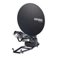
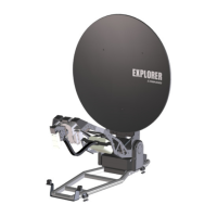
Description of the system components
98-145510-E Chapter 2: Introduction 2-6
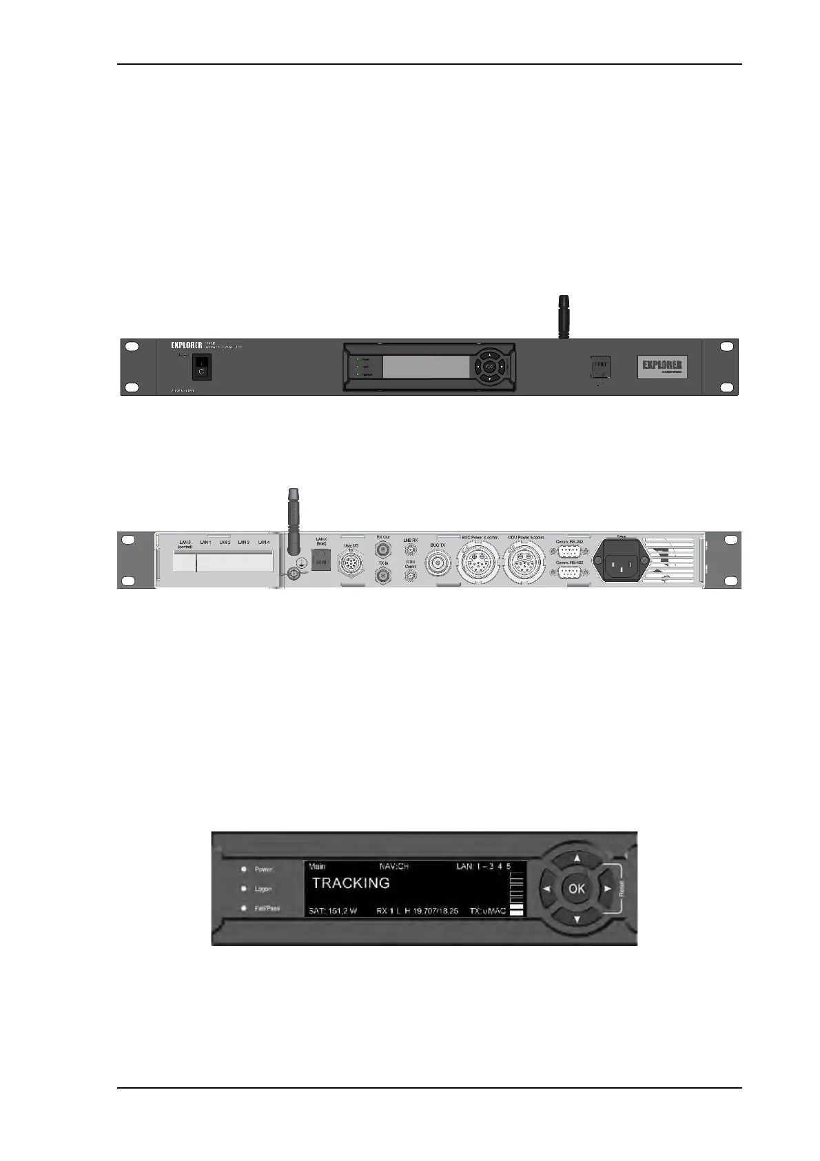
2.2.3 Antenna Control Unit (ACU)
ACU
The ACU manages all communication between the antenna and the connected modem.
The ACU has status LEDs, a display and a keypad. It also provides a flexible configurable
LAN interface (DHCP client/server, static IP address etc.) and a built-in web interface for
configuration of the system. The ACU comes in two versions, a 500 W version and a
1000 W version.
For details of the interfaces of the ACU, see Interfaces of the Antenna Control Unit (ACU)
on page 4-1.
2.2.4 Keypad and display
Using the keypad and display on the ACU you can deploy, stow and stop the antenna,
including monitoring the system (warnings, errors and information). See Keypad and
display menus on page 6-27 for a full list of menus and details on how to use the display
and keypad.
The menus show how the system has been configured. You can also see events (warnings,
errors and information). Signal strength indication is rendered on the display as 7 blocks on
the main display.
The display has a two line menu system. The display also supports two status lines (Upper
and Lower) for compact satellite and antenna information. For a description of the LED light
indicators see LEDs on the keypad of the ACU on page 7-8.
Figure 7: ACU front panel
Figure 8: ACU connector panel
Figure 9: Keypad and display (detailed, example)
 Loading...