Interfaces of the antenna
98-145510-E Chapter 4: Interfaces 4-9
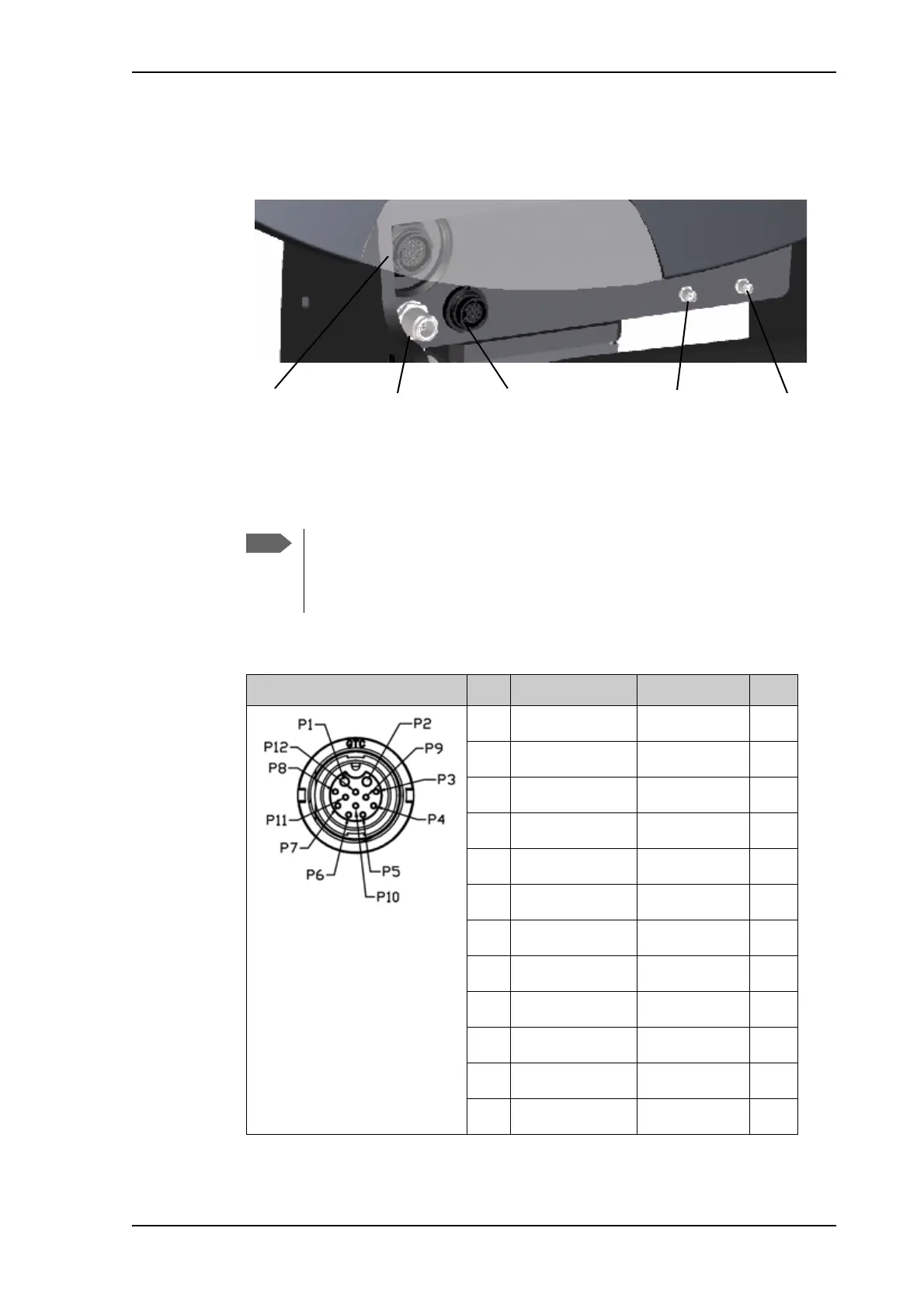
The connectors on the front of the antenna are partially hidden behind the reflector as
shown.
• Pol-unit. GTC C4 female connector for connecting to the Pol-unit.
• BUC-TX: N-connector for signal and power from the antenna control box to the BUC.
• BUC M&C (Monitor & Control). GTC C3 female connector for DC power and
communication between the antenna control box and the BUC.
Figure 14: Connectors on the front of the antenna
Remember to configure the system for the BUC connector you are using (N-
connector alone or M&C connector and N-connector). See antenna_data
buc on page D-4. Also remember to use the corresponding connectors on the
ACU (BUC TX and/or BUC Power & Comm.).
Outline Pin Pin function Wire color AWG
1BUC Power Black/Red 14
2BUC Power RTNBlack/White14
3GND Drain wire -
4NC NC -
5BUC Serial RX-Red 22
6BUC Serial RX+Orange 22
7 BUC Serial TX- Yellow 22
8 BUC Serial TX+ Green 22
9 Keyline - Blue 22
10 Band select + gray 22
11 Keyline + Purple 22
12 Band select - White 22
Table 4-15: Pinout for BUC M&C connector on antenna front
LNBGNSSBUC M&CBUC-TXPol-unit