Chapter 2: Installation
98-141368-A 31
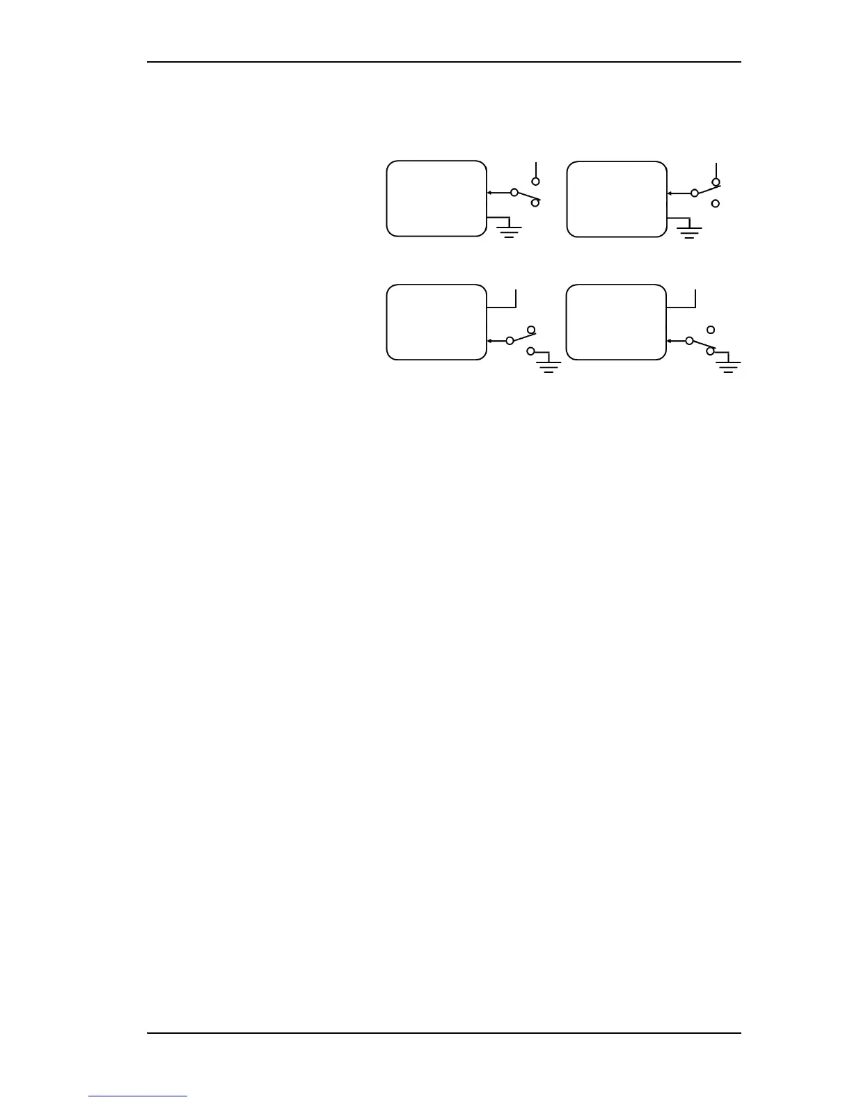
Input pin 5/8 (example):
The functions of the I/O pins are as follows:
Pin 5/8: Ignition input.
The ignition function can be used to turn on/off the terminal by means of an external signal.
The external signal that triggers the ignition function can be either positive DC voltage or
ground. The ignition function uses pin 5 together with pin 8 (DC in). Connect the appropriate
pin to the ignition switch as follows:
• Active high (default): Connect pin 5 permanently to ground. When the ignition is on,
connect pin 8 to positive DC voltage (10.5-32 V DC). When the ignition is off, disconnect
pin 8 from the positive DC voltage.
• Active low: Connect pin 8 permanently to positive DC voltage (10.5-32 VDC). When the
ignition is on, connect pin 5 to ground (< 1.2 V DC). When the ignition is off, disconnect
pin 5 from ground.
Pin 6: Ground.
(Non-configurable) Pin 6 can be used as an external connection to ground. Pin 6 is connected
to ground inside the terminal.
Pin 7: DC output.
(Non-configurable) Pin 7 can be used as a DC output. The voltage on pin 7 is 9-15 V and the
output can supply up to 50 mA. Pin 7 can be used as power supply to a relay, ringer or similar.
The built-in web interface of the terminal offers a page for configuring the I/O pins. For
information on how to configure the I/O pins, see To configure the I/O interface on page 72.