Adjustments
HF SSB Transceiver 9323/9360/9390/9780 Technical Service Manual 7-25
q Select a value for the HIGH PWR SOT resistor R16 (nominally 8k2 to 12k)
on the PA PCB for the following output power.
PA assembly 08-04963
(2 to 26.5 MHz)
100 watts PEP, link X fitted
125 watts PEP, link X should not be
fitted.
PA assembly 08-05237
(2.25 to 30.0 MHz or
1.6 to 30 MHz with
option LF fitted)
125 watts PEP, link X fitted
©
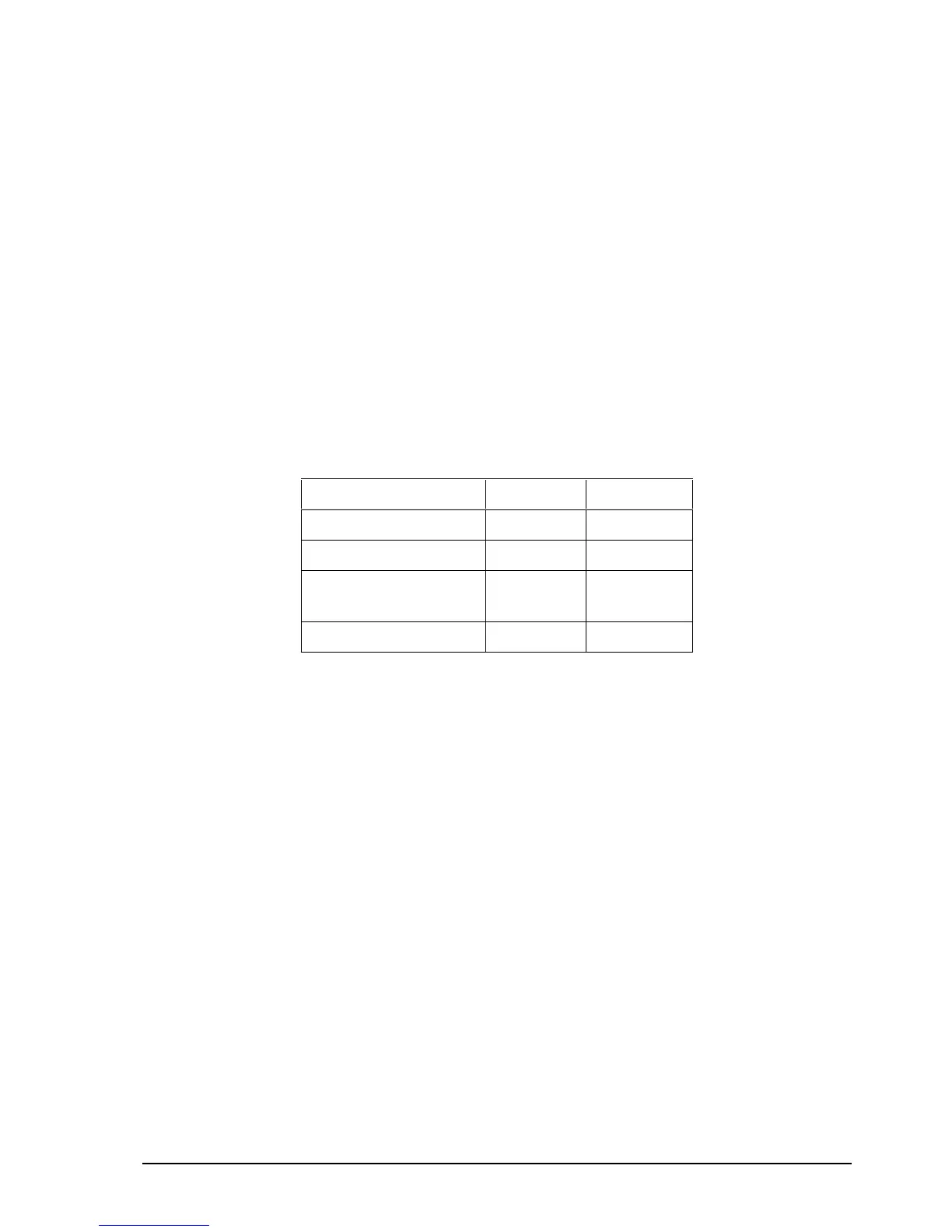
The indicated PEP level with two-tone modulation will depend upon the type
of measuring instrument as shown in Table 7-7.
Table 7 -7: Power output PEP vs measuring instrument
Power output PEP 100 Watt 125 Watt
Peak reading meter 100 W 125 W
RMS reading meter 50 W 62.5 W
Average reading meter
(e.g. Bird Model 43)
40.5 W 50.6 W
Oscilloscope 200 V PP 224 V PP
q Check the two-tone waveform is clean and undistorted.
q The output power is factory set and not likely to be outside the specified
limits. Check that there are no faults with the transmitter circuits before
attempting to adjust the power output.
Output power 27 MHz band (9323 only)
Before setting the lower power required for the CB channels, set the high power
(see page 7-24, Output power).
Setting the output power for the 27 MHz band
q Select test channel 19 [1 08-04963] or test channel 20 [1 08-05237].
Both channels are 27 MHz.
q Proceed as detailed on page 7-24, Output power.
q Select a value for SOT R17 for less than 12 W PEP (5 W average).
q Check the two-tone waveform is clean and undistorted.