HF SSB Transceiver 9323/9360/9390/9780 Technical Service Manual 9-1
9 Drawings
The drawings in this chapter consist of the mechanical and electrical diagrams
required to maintain the 9323, 9360, 9390 or 9780 transceiver.
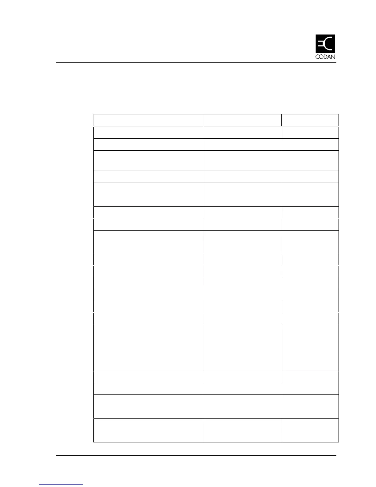
Table 9 -1: List of drawings
Title Drawing Drawing No
Control Head Layout
16-00109-001
Transceiver Layout
16-00109-002
9323, 9360, 9390 & 9780 Block
Diagram
03-00902
Interconnection Diagram
04-02971
Display Panel
Circuit Diagram 04-02974
PCB Assembly 08-04964
Microphone & Keyboard Encoder
Circuit Diagram 04-02975
PCB Assembly 08-04965
Microprocessor & Audio
Micro & I/O Circuit Diagram 04-02976 Sht 1
Tx Audio Circuit Diagram 04-02976 Sht 2
Rx Audio & S’Call Circuit Diagram 04-02976 Sht 3
Microprocessor & Audio Assembly PCB Assembly 08-04966
Rx/Exciter
RF Mixer and Synthesiser Circuit Diagram 04-02972 Sht 1
455 kHz IF Mod & Demod Circuit Diagram 04-02972 Sht 2
Receiver/Exciter Assembly PCB Assembly 08-04962
RF Mixer and Synthesiser Circuit Diagram 04-03135 Sht 1
455 kHz IF Mod & Demod Circuit Diagram 04-03135 Sht 2
Receiver/Exciter Assembly PCB Assembly 08-05322
PA & Filter
Circuit Diagram 04-02973
PCB Assembly 08-04963
PA & Filter (30 MHz)
Circuit Diagram 04-03096
PCB Assembly 08-05237
Filter, Low-pass (1.6 MHz)
Circuit Diagram 04-03093
PCB Assembly 08-05227