Brief description
3-2 HF SSB Transceiver 9323/9360/9390/9780 Technical Service Manual
General
Read this description of the 9323, 9360, 9390 or 9780 transceiver in conjunction
with the Block Diagram 03-00902.
The 9323, 9360, 9390 or 9780 transceiver uses the same double conversion in
Receive and Transmit modes. Only the 45 MHz band-pass filter, the 455 kHz
sideband filter and the local oscillators VCO1 and VCO2 are common to both
modes of operation. The signal routing is determined by switching and control
voltages according to the mode selected.
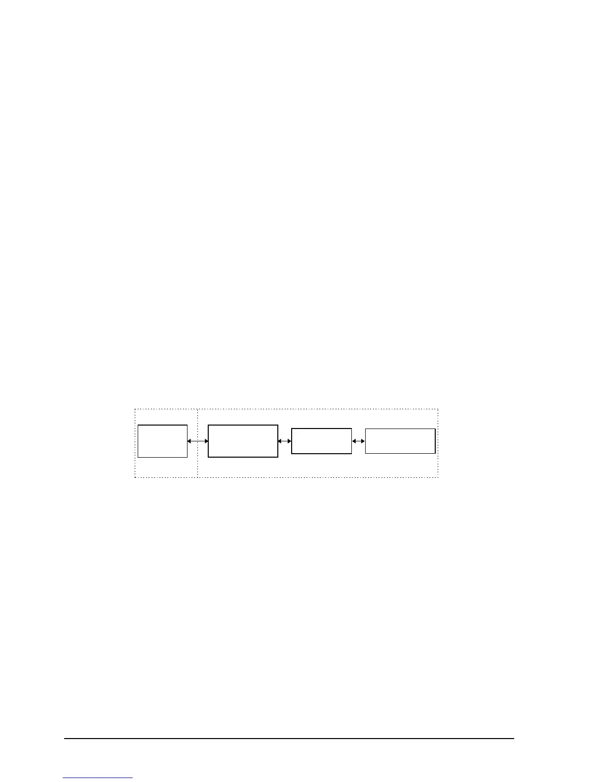
The circuits and functions of the 9323, 9360, 9390 or 9780 are located on four
major PCBs as shown in Figure 3-1:
• Display panel PCB
• Microprocessor and audio PCB
Micro and I/O
Transmit audio
Receive audio and Selective call
• Rx/Exciter PCB
RF Mixer and synthesiser
455 kHz IF modulator and demodulator
• PA and Filter PCB
Microprocessor
and Audio
Display
Panel
Rx/Exciter