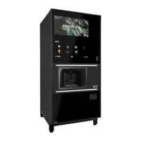
CABINET INTERIOR
18. Access to the components and equipment in the rear section of the cabinet is obtained by
removing the ingredient canisters and the relevant back panel.
19. Cold water mains supply enters the cabinet through an aperture in the rear panel and
connects to a twin chamber inlet valve for the hot water supply. There is also a similar twin
chamber inlet valve dedicated to the cold-water supply. This is fitted only in the case where
a cold drinks system is required.
20. A length of tubing takes the water supply from the inlet valve into the water heater tank,
located at the top of the cabinet. Hot water in the correct quantity is then directed from the
tank to the appropriate mixing bowl via a solenoid operated dispense valve. A dispense
valve is associated with each ingredient. Any overflow from the tank is directed into the
waste bucket via an overflow tube. Fitted to this tube is a high temperature cut-out (or two
cut-outs, depending on the model) which, when operated, cuts off the electrical supply to
the heater in the tank. The cut-out must then be reset to restore the supply. Another length
of tubing facilitates draining of the heater.
21. The Carbonator is provided with three inputs: cold water from the inlet valve; two types of
syrup, pumped from the syrup containers; and carbon dioxide from the CO
2
cylinder. Still or
carbonated water and syrup are taken from the carbonator, via separate tubes, to the
dispense head.
22. A level probe is fitted to the rear of the cabinet door and a similar device is in the fresh brew
waste container. When the door is closed these devices act as contact probes allowing the
units control system to monitor the liquid level in the waste containers.
23. Two printed circuit boards are fitted to the top right-hand side of the cabinet rear panel: the
DC Remote Input/Output Board (DC RIO) and the Power Supply Unit (PSU). The DC RIO
Board provides the high current drives to operate the output devices (valves, motors, etc.)
in response to signals from the Controller Board.
24. A solid-state relay, located beneath the printed circuit boards, pulses current to the heater
in response to signals from the DC RIO Board. The DC RIO Board receives signal from the
Controller Board via an I
2
C link. The temperature of the water in the boiler is measured by
the Controller Board using an NTC thermistor mounted at the end of a stainless-steel probe
immersed in the hot water tank.

 Loading...