Install the Communication Card to the PC
CAUTION: Electrostatic discharge (ESD) can damage the electronic components of the Cognex hardware; wear a
grounded, static-dissipating wrist strap for ESD protection.
1. Power off the PC and remove its cover.
2. Select a PCI Express x1 slot. Remove the slot cover and store it for future use.
3. Press the board into the slot until it is firmly seated.
4. Replace the PC's cover.
CAUTION: Do not power on the PCuntil you have connected any I/O devices to the Communication card.
Connect I/O Devices (Optional)
The Communication card supports the connection of PLCs and photoelectric sensors, as well as general use I/O
devices, such as relays, indicator lights and reject mechanisms. The Communication card also supports connection to
either a single-ended or differential encoder. For more information, refer to Inputs on page14, Outputs on page15 and
Encoder Inputs on page16.
There are two options for connecting I/O devices: using the accessory Breakout cable; or the I/OTerminal Block cable
and DIN-rail mountable Terminal Block accessories.
l If connecting the Breakout cable to the Communication card, the cable's flying lead wires can be connected
directly to the applicable I/O device.
l If connecting the I/O Terminal Block cable to the Communication card, the cable is connected to the Terminal
Block, which can be connected directly to the applicable I/O device.
Connect the Breakout Cable
1. Determine how I/O devices will be connected to the Communication card's inputs and outputs. Refer to Wire
Inputs and Outputs on page27 for common wiring configurations.
2. Make sure all I/O devices and the PC hosting the Communication card are powered off.
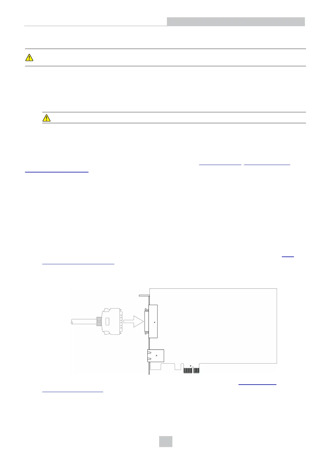
3. Connect the Breakout cable's MDRconnector to the MDR connector on the Communication card.
4. Connect the Breakout cable's flying lead wires to the applicable I/O device. Refer to Breakout Cable
Specifications on page20 for cable pin-outs.
10
Installation