Wire Inputs and Outputs
The following figures show basic wiring for some of the more common I/O configurations.
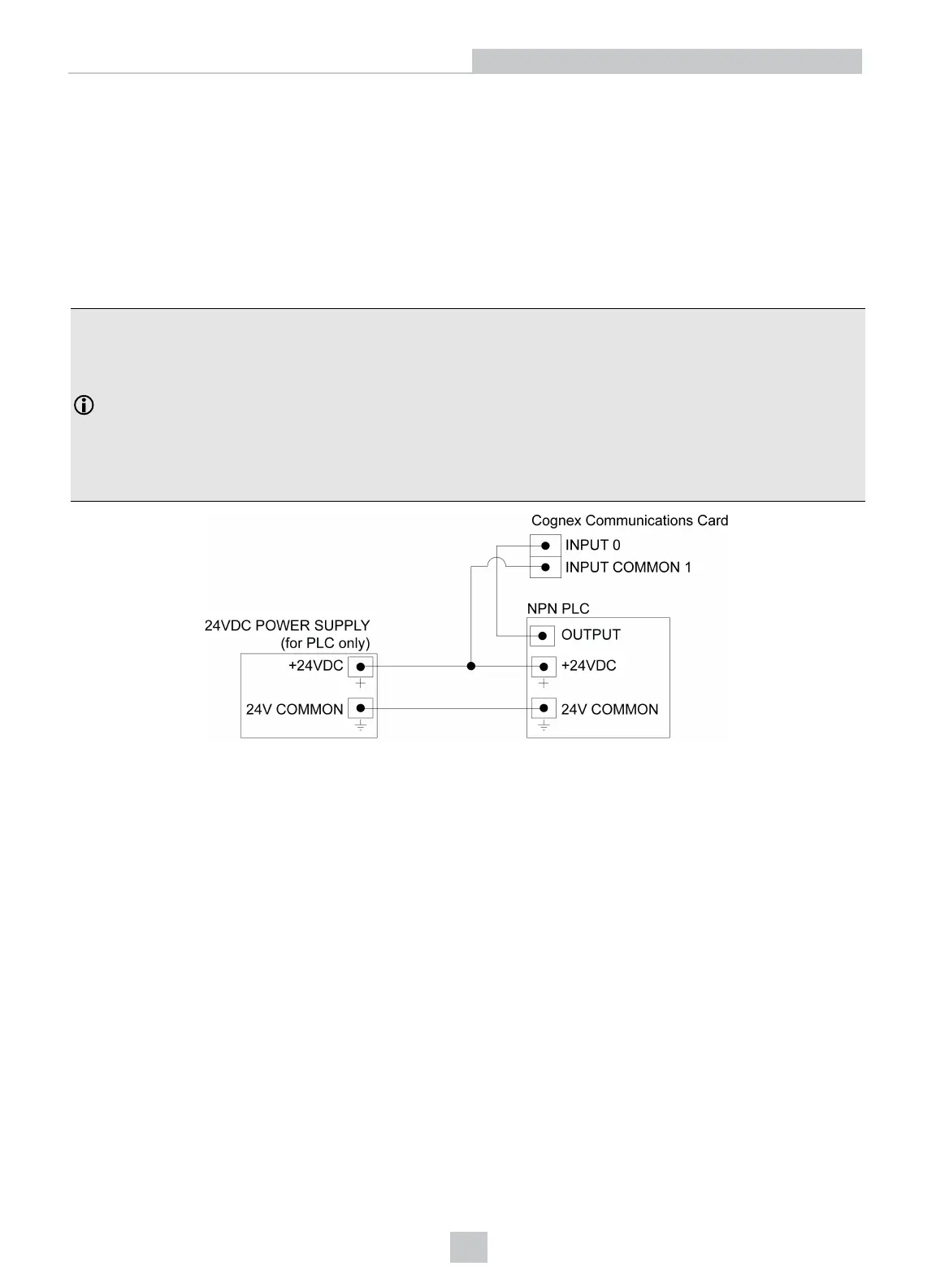
Input from PLC - Current Sinking
To configure the input as a sinking input, connect INPUT COMMON (for example, INPUT COMMON 1) to the high voltage
reference (+24VDC) and connect one of the INPUTS (for example, INPUT 0) to the OUTPUT of the photoelectric sensor
or PLC. When the PLC output turns ON, the INPUT is pulled down to a low voltage level.
Note:
l The inputs are typically connected (directly or indirectly) to a PLC or photoelectric sensor.
l There are two sets of inputs: INPUTS 0 - 3 share the INPUTCOMMON 1 connection and INPUTS 4 - 7 share
the INPUTCOMMON 2 connection. Therefore the input devices for each set of inputs must be the same;
either current sinking or current sourcing.
l To maintain optical isolation of the I/O lines, the devices connected to these lines must not be connected to
the same power supply as the PC. If they are connected to, or share a ground with, the same power supply,
they may still function but will no longer be optically isolated.
27
Wire Inputs and Outputs