Connect the I/O Terminal Block Cable and Terminal Block
1. Determine how I/O devices will be connected to the Communication card's inputs and outputs. Refer to Wire
Inputs and Outputs on page27 for common wiring configurations.
2. Make sure all I/O devices and the PC hosting the Communication card are powered off.
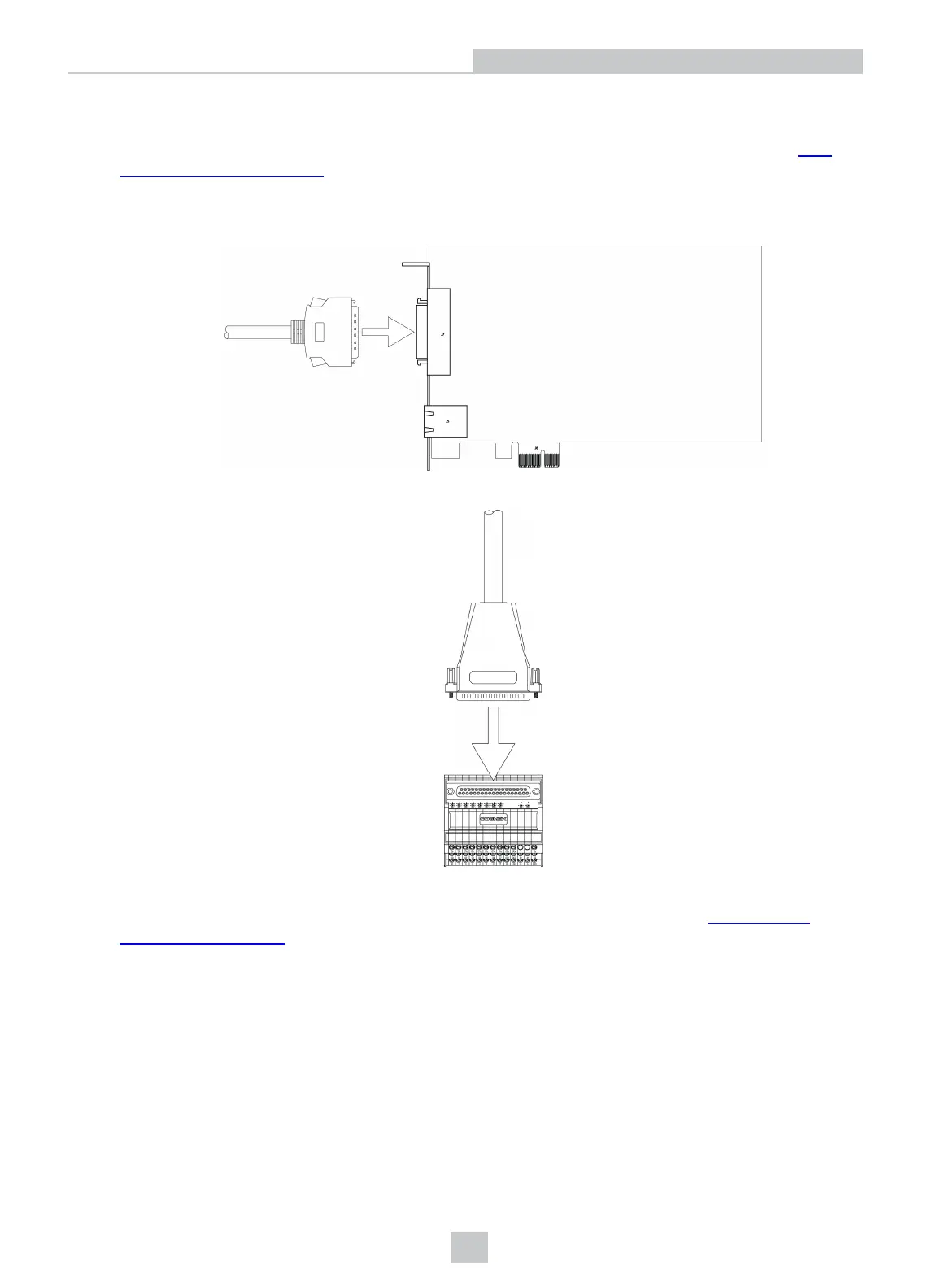
3. Connect the I/O Terminal Block cable's MDRconnector to the MDR connector on the Communication card.
4. Connect the I/O Terminal Block cable's DB37 connector to the DB37 connector on the Terminal Block.
5. Attach the Terminal Block to a convenient surface. It is configured for NS 35 DIN rail mounting.
6. Use a screwdriver to loosen the M3 wire retention screws on the Terminal Block. Refer to Terminal Block
Assignments on page24 for terminal block pin assignments.
7. Insert the input, output and encoder wires (12- 24 AWG, solid or stranded wire) into the terminals.
8. Tighten the wire retention screws to secure the wire leads in the Terminal Block; the maximum torque is 0.5 Nm to
0.6 Nm (4.4 in-lb to 5.3 in-lb).
9. Connect the other end of the input, output and encoder wires to the applicable I/O device.
11
Installation