15. Sensors
15.1. Sensor fail detection (FLS)
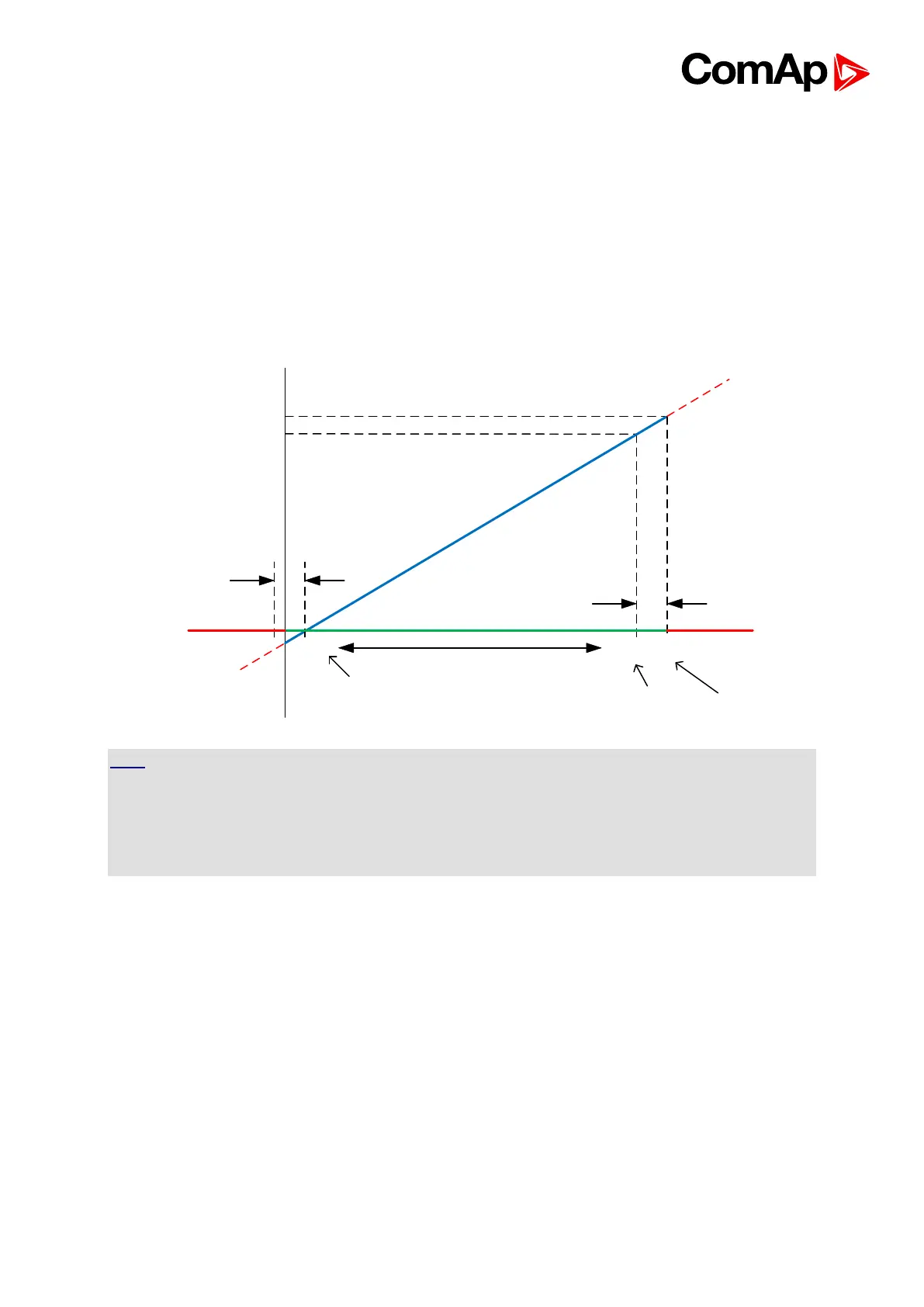
If the measured resistance, voltage or current on an analog input gets out of valid range, the
sensor fail will be detected and a sensor fail message will appear in the alarmlist. The valid
range is defined by the most-left (R
L
) and most-right (R
H
) points of the sensor characteristic
±12.5% from R
H
-R
L
.
12.5% of the
sensor
range (25Ω)
Sensor fail limit would be
-15 Ω what is physically
imposible so sensor fail is
not detected even for 0 ohm
First point of
the curve
100% of the sensor range
Last point of
the curve
Sensor fail
limit
Sensor fail area
10
11,25
Bar
10
210
235
Ω
12.5% of the
sensor
range (25Ω)
-15
HINT
The sensor fail alarm does not influence the gen-set operation. Sensor fail does not activate
Binary output Alarm.
If engine shutdown/stop is required when Fls appears, configure in GenConfig ->
Inputs/Outputs -> Analog inputs -> Protection -> property “Active when” to Under/Over limit +
Fls.
15.2. Default Sensors
There are several predefined sensors which can be used for connection of particular sensor
to analog inputs of the controller. The following list shows predefined standard sensors which
are available in the roller menu.
PT100/°C, PT1000/°C, PT100/°F, PT1000/°F, NI1000/°C, NI1000/°F, 4-20mA active (linear),
0-2400ohm (linear), 0-2.4V (linear), Tristate (for definition please see the chapter about wiring
Analog Inputs)
If you click on Other sensors, following dialog is shown: