• Input output address is displayed on the front panel LED’s
• Use PC configuration tool to configure controller according external modules setting
IS-BIN16/8 module has two separate CAN1 addresses for binary inputs Group 1, Group 2 and
binary outputs Group (total three addresses). The CAN1 address for BI Group 1 and for BO
Group 2 can be adjusted on the IS-BIN16/8. The address for BI Group 2 is set automatically
to the address following BI Group 1.
HINT
If part of IS-BIN16/8 is not required for use, CAN address 0 disables corresponding CAN
message (group data are not send).
11.2.1. IS-AIN8, IS-BIN8/16 address setting
• Press Address button during IS-AIN8 power supply on to switch to addressing mode.
• Then repeatedly press or keep pressed address button to adjust required address
according to controller configuration.
• After setting requested address, release the buttons and wait until the digits blink – it
indicates write the changed address to EEPROM memory.
11.2.2. IS-AIN8, IS-BIN8/16 SW version check
Let suppose IS-AIN8 of SW version 1.4 for this example. Shortly press address button.
Following sequence appears on the display: number “1”, one second pause, number “4”, two
second pause, number “1”, one second pause, number “4”, two second pause and finally IS-
AIN8 actual address.
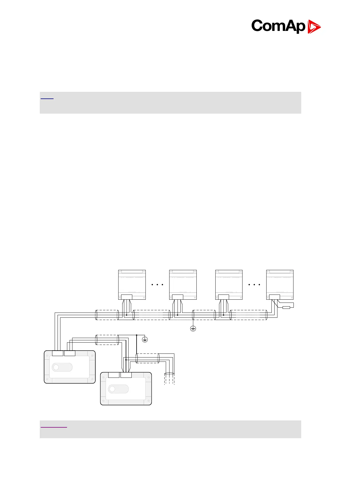
11.2.3. Example of Wiring