13. CAN Bus
13.1. CAN bus Tx, Rx LED indication
Tx and Rx LED is connected directly to Tx and Rx signal.
13.2. CAN and RS485 bus wiring
The wiring of the CAN bus communication should be provided in such a way that the following
rules are observed:
• The maximum length of the CAN bus depends on the communication speed. For a
speed of 250 kbps, which is used on the CAN1 bus (extension modules, ECU) and
CAN2 bus if it is switched to 32C mode, the maximum length is 200 m. If the CAN2 bus
is switched to 8C mode the speed is 50 kbps and the maximum length is 800 m.
• The maximum length of the RS485 bus is 1000 m
• The bus (CAN and RS485) must be wired in linear form with termination resistors at
both ends. No nodes are allowed except on the controller terminals.
NOTE:
A termination resistors at the CAN and RS485 are already implemented on the PCB.
For connecting, close the jumper near the appropriate CAN or RS485 terminal. For
more information on jumper settings please refer to the section 3.1.4 Jumper setting.
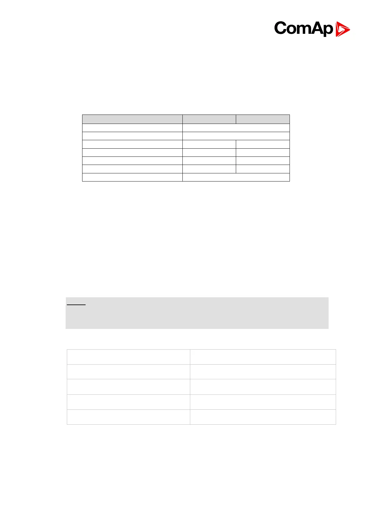
• Use a cable with following parameters: