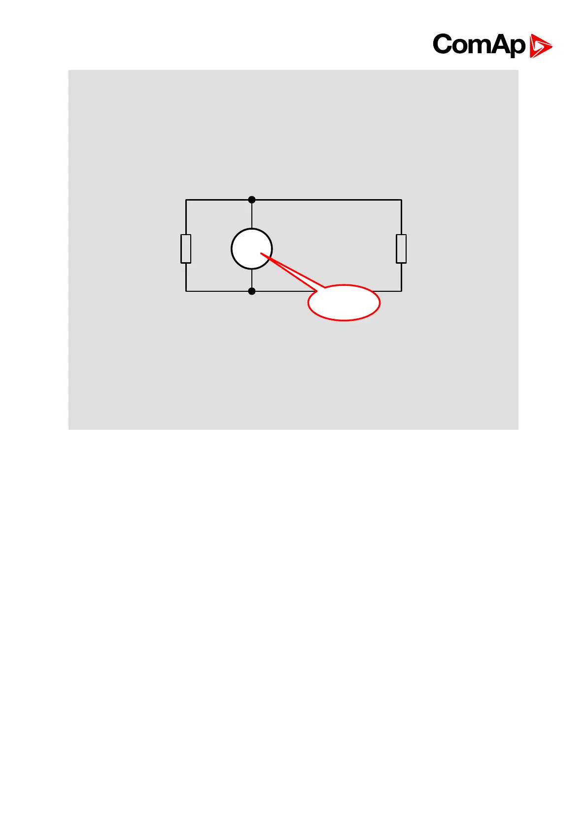
Always check the number and placement of terminating resistors in the CAN bus line, only
correct wiring ensures reliable operation! Resistors must be placed at either end of the line
(see picture), and correct number of resistors must be used! Correct number can be checked
using ohmmeter - when power supply for ALL devices on the CAN bus line (including third
party, e.g. ECU) is switched off, the resistance measured between A and B wire should be 60
Ohms.
For longer distances is recommended to connect one CAN COM terminal (one connection for
whole site) and cable shielding to the ground in one point.
External units can be connected on the CAN bus line in any order, but line arrangement (no
tails, no star) is necessary.
Recommended CAN bus data cables see in Chapter Technical data.
IG-MU and IG-IB units are connected to CONTROLLER CAN2 bus.
11.3. IGS-PTM and IGL-RA15
It is possible to connect up to four IGS-PTM and one IGL-RA15 to one controller. IGS-PTM
can be connected to the controller like IS-AIN8 and IS-BIN16. IGS-PTM behaves like IS-AIN8
and IS-BIN16/8 modules in one unit. IGS-PTM and IGL-RA15 units contain internal jumper
removable 120-ohm resistor.
11.3.1. Example of Wiring