10
Rev. 1 | 01/2020 | MS Safety Module | © 2020 | Comepi srl
EN
6.2 Operating modes
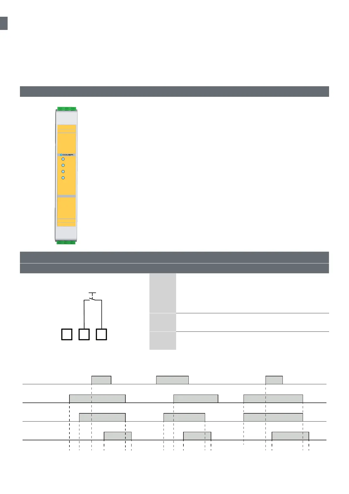
6.2.1 Manual start
X3 X2 X1
Start
A
The start button is connected between X1 and X2.
The safety inputs S12 and S22 are operated:
• contact closed between S11 and S12
• contact closed between S21 and S22
The start button is pressed and the safety outputs switch ON
B
The opening of at least one safety input contact forces
immediately the safety outputs to the open state
C
A new operating cycle is possible only after releasing both
input contacts and then operating them again
Reset / Start
Input ch 1
Input ch 2
Safety output
Ts
∞
Ta
<160ms
Tr
<20ms
Ts Ta
Tr
Ts Ta
Tr
The MS1A20-024 module monitors emergency stops, limit switches, magnetic switches according to 2006/42/CE Machinery
Directives.
The MS1A20-024 is also used for oor levelling and relevelling of lift cabin, according to the 2014/33/EU Lift Directive, in lift
applications.
6. MS1A20-024
X1-X2: manual start / automatic start
X1-X3: monitored manual start
S11-S12: channel 1 NO input
S21-S22: channel 2 NO input
A1: power supply 24 Vdc (+)/Vac(~)
A2: power supply 24 Vdc (-)/Vac(~)
13-14: NO safety output
23-24: NO safety output
6.1 Terminal layout
sdnaH 2 eludom ytefas
eludoM ytefaS
Power
Input 1
Input 2
Channels
X3
A2
A1
X2
S22
S12
X1
S21
S11
13
23
14
24
MS1A20-024