30
Rev. 1 | 01/2020 | MS Safety Module | © 2020 | Comepi srl
EN
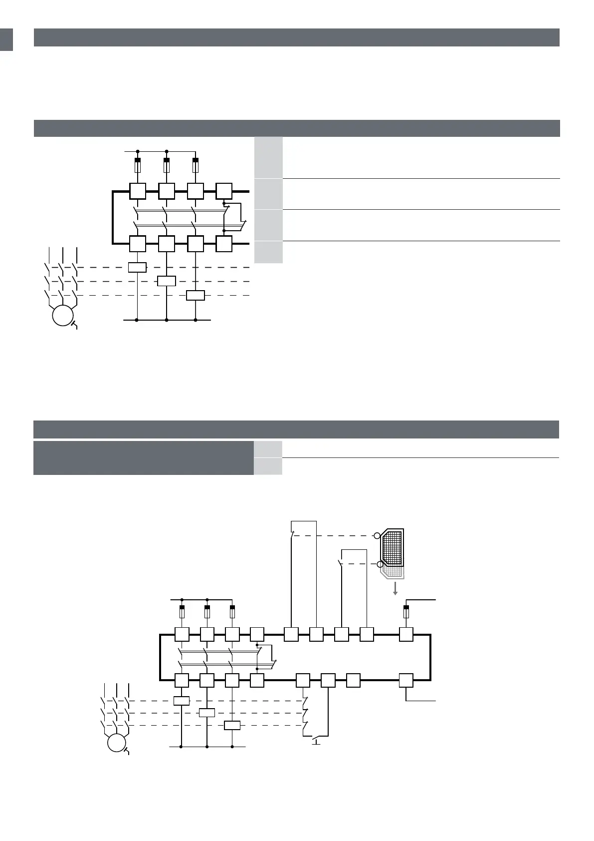
8.5.1 E-gate, safety limit switch and one
access monitoring (double channel mode)
A
A cross circuit between the two channels will be recognized
B
In case of a fault the safety outputs will switch OFF
8.5 Application
Not only must the output be safe, but also the complete wiring and surroundings. In order to reach cat. 4 of functional
safety, two outputs must be wired as a pair, so that a defect of one output cannot cause a total loss of safety, as the other
one of the pair is still able to switch o the dangerous parts of the plant (or machine). So wiring similar to the following
has to be done:
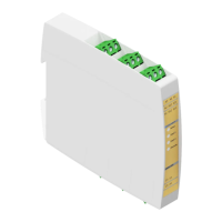
8.4.1 Outputs function
A
The NO safety outputs switch on (contacts close) and the NC
auxiliary output opens, when the safety inputs are active and
the start/reset is pressed.
B
In case of intervention of the safety inputs the NO safety outputs
are switched o and the NC auxiliary output is closed.
C
If the power supply fails, the NO safety outputs are switched
o and NC auxiliary output is closed.
D The NC auxiliary output is not a safety output
8.4 Function description
A1
A2
X1 X2 X3
S11 S12 S21 S22
13
14
23
24
33
34
41
42
M1
3~
M
K1
K2
K3
L
N
E-STOP
Pwr 24V (+/~)
Pwr 24V (-/~)
Manual start
L
Pwr 24V (+/~)
A2
X1 X2 X3
14 24 34 42
M1
3~
M
K1
K2
K3
N
Pwr 24V (-/~)
A1
S11 S12 S21 S22
13 23 33 41
Manual start