8
Rev. 1 | 01/2020 | MS Safety Module | © 2020 | Comepi srl
EN
4.1 Power supply
4.2 Wiring
4. Wiring
24Vdc ± 10%; 24Vac -15%/+10%, 50÷60 Hz, Class 2, overvoltage category III.
1
Warning:
Max. terminal tightening torque: 0.5Nm (for all connections)
2
Warning:
Switch power supply OFF before wiring the device
3
To prevent contact welding, a fuse should be connected on the output contacts.
Sufficient fuse protection must be provided on all output contacts with capacitive and inductive
loads.
Ensure the wiring and EMC requirements of IEC 60204-1 are met.
4
Information:
It is good practice to separate the power supply of the control unit from that of other electrical
devices (e.g. frequency drives, electric motors, inverters) or other sources of disturbance.
5
Information:
Use conductors with section: 0,2 - 2,5 mm² (24 - 14 AWG)
6 Do not exceed the electrical ratings.
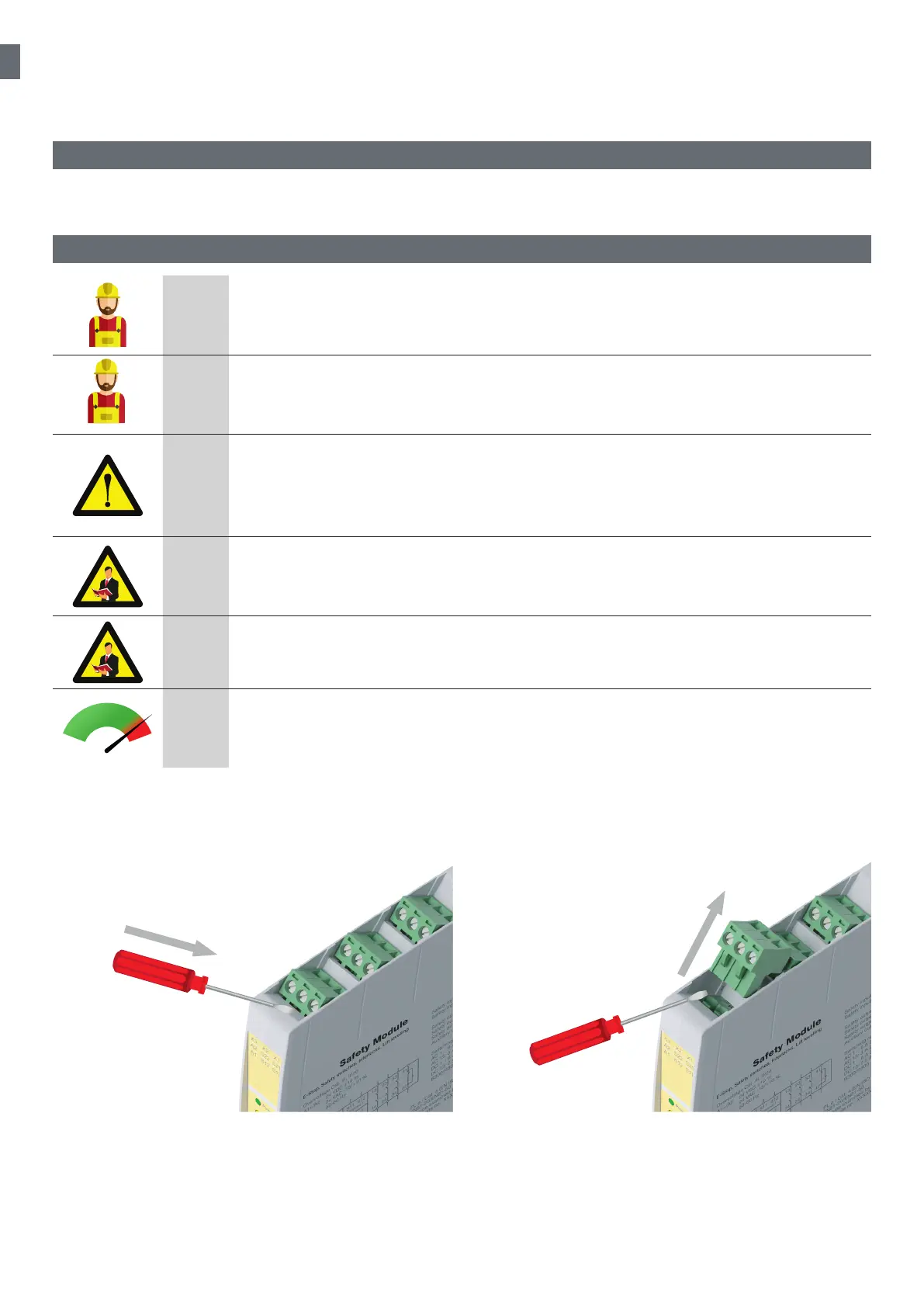
The safety modules are equipped with pluggable terminal blocks for easy wiring and devices exchange.
Procedure:
• Switch power supply OFF before wiring the device
• Insert the screwdriver in the recess of the terminal block and lift it to remove it. Do not remove the terminals blocks by
pulling the cables!
• Once the wiring of the terminal block is completed, insert the terminal block into the respective position
The plug-in terminal blocks are coded, so to prevent inserting the terminal blocks in the wrong position.
1
2