THEORY
OF
OPERATION
1.
Initialization
Sequence
When
power
is
applied or
~
signal is
input,
the
printer
executes
the
following
initialization:
1. Resets
the
control
circuit.
2. Generates and stores a
print
start
timing
value by
moving
the
print
head
twice.
3. Brings
the
print
head
back
to
the
home
position.
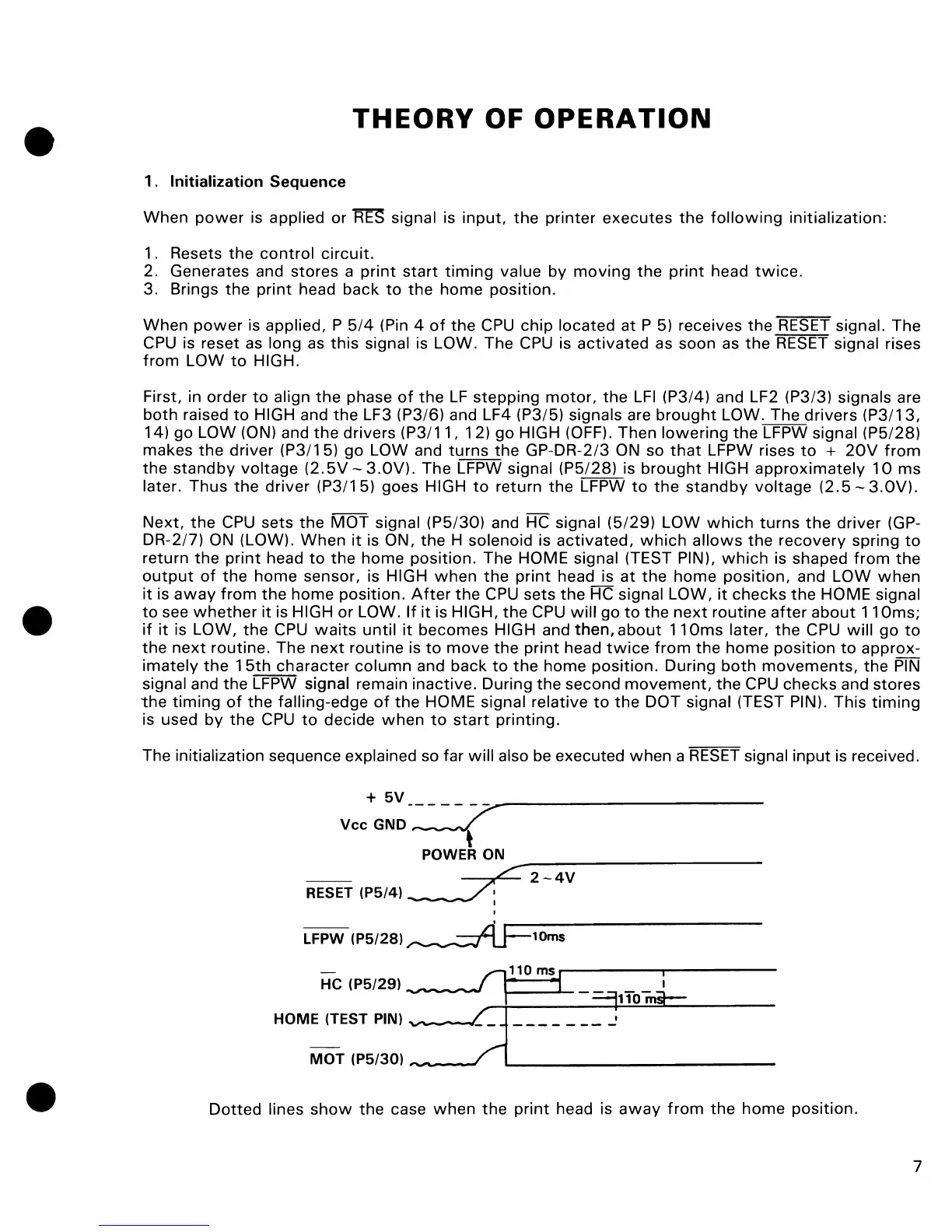
When
power
is applied, P
5/4
(Pin 4
of
the
CPU
chip
located
at
P 5) receives
the
RESET signal. The
CPU is reset as long as
this
signal is LOW. The CPU is
activated
as soon as
the
RESET signal rises
from
LOW
to
HIGH.
First, in order
to
align
the
phase
of
the
LF
stepping
motor,
the
LFI
(P3/4) and LF2 (P3/3) signals are
both
raised
to
HIGH and
the
LF3 (P3/6) and LF4 (P3/5) signals are
brought
LOW. The
drivers
(P3!13,
14) go
LOW
(ON) and
the
drivers
(P3!11,
12)
go
HIGH (OFF). Then
lowering
the
LFPW signal (P5/28)
makes
the
driver
(P3/15)
go
LOW and
turns
the
GP-DR-2/3 ON so
that
LFPW rises
to
+
20V
from
the
standby
voltage
(2.5V
-
3.0V)'
The LFPW signal (P5/28) is
brought
HIGH
approximately
10
ms
later.
Thus
the
driver
(P3!15)
goes HIGH
to
return
the
LFPW
to
the
standby
voltage
(2.5
-
3.0V).
Next,
the
CPU
sets
the
MOT
signal (P5/30) and HC signal (5129)
LOW
which
turns
the
driver
(GP-
DR-2!7) ON (LOW).
When
it
is ON,
the
H solenoid is
activated,
which
allows
the
recovery
spring
to
return
the
print
head
to
the
home
position.
The HOME signal (TEST PIN),
which
is shaped
from
the
output
of
the
home
sensor, is HIGH
when
the
print
head is
at
the
home
position,
and
LOW
when
it
is
away
from
the
home
position.
After
the
CPU sets
the
HC signal LOW,
it
checks
the
HOME signal
to
see
whether
it
is HIGH
or
LOW.
If
it
is HIGH,
the
CPU
will
go
to
the
next
routine
after
about
11
Oms;
if
it
is LOW,
the
CPU
waits
until
it
becomes
HIGH and
then,
about
11
Oms later,
the
CPU
will
go
to
the
next
routine. The
next
routine
is
to
move
the
print
head
twice
from
the
home
position
to
approx-
imately
the
15th
character
column
and
back
to
the
home
position.
During
both
movements,
the
PIN
signal and
the
LFPW signal remain inactive. During
the
second
movement,
the
CPU
checks
and stores
the
timing
of
the
falling-edge
of
the
HOME signal relative
to
the
DOT
signal (TEST PIN). This
timing
is used by
the
CPU
to
decide
when
to
start
printing.
The initialization sequence explained so far
will
also be executed
when
a
RESET
signal
input
is
received.
+
5V
VCCGND-~
POWER
ON
-,,;:-~-
2 -
4V
RESET
(P5/41 _ _
/0
~
I
LFPW
(P5/281~10ms
n110ms
i
He
(P5/291
---
~
i 1 -
=,110mi--
HOM:~:~:5::::==:-~~-_-
__
-_-_-
__
-_-_-_'
____________
__
Dotted
lines
show
the
case
when
the
print
head is
away
from
the
home
position.
7