CommScope ERA
®
CAP MX Medium Power Carrier Access Point Installation Guide M0203A5A_uc
Page 40 © November 2020 CommScope, Inc.
Installing CAP MXs
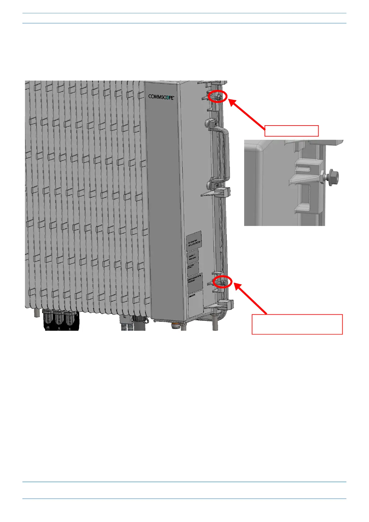
7 From both sides of CAP MX-1:
a Loosen the M6 lock nuts, as shown below, to provide adequate space for the mounting bracket.
b Remove the two M6 screws and their M6 plain and M6 split-lock washers; reserve the screws and
washers as you will later reinstall them.
Remove M6x12 bolt and
the washers
Loosen M6 pin