CommScope Instruction Guide
860647713, Rev B, V.05
Page 26
38 Pages
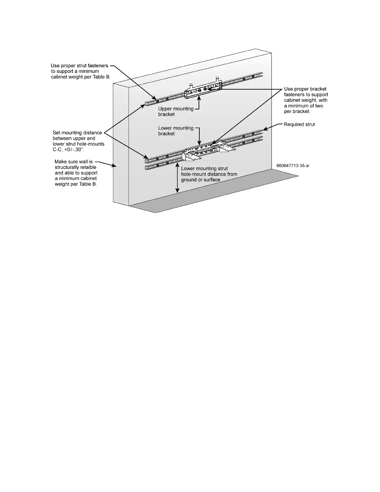
Figure 37. Fasten Upper and Lower Mounting Brackets to Wall-Mounted H-Frame
To mount the brackets to an H-Frame on poles (Figure 38):
Note: Make sure the poles and frame can support a minimum cabinet weight per Table C and are
structurally reliable.
1. Mark position of the lower strut first to required cabinet mounting distance above ground level.
2. Mark position of hole-to-hole distance between upper and lower struts and set hole distance between
upper and lower struts plus or minus 0.30" C-C as given per Figure 35.
■ For CMC-21 at 38.62" per example in Figure 38
■ For CMC-28 at 50.87" per example in Figure 38
3. Drill the mounting holes and fasten the struts to the poles with customer provided hardware.
4. Fasten the upper and lower mounting brackets to the H-frame struts, Figure 38.
— Fasten additional required strut above the lower strut; Figure 35, Figure 36, Figure 38.
5. Verify that upper and lower mounting brackets are vertically align C-C with each other, Figure 35.