CommScope Instruction Guide
860647713, Rev B, V.05
Page 28
38 Pages
4. Locate the M10 (1.5 x 25 mm) screws, flat and lock washers from kit 760242250 (Table F ) or
760242247 (Table G) and loosely fasten screws in place for rear or side mount. Install shims as
required between lower bracket and bottom of cabinet such that the lower bracket supports cabinet
weight and not the upper bracket.
Note: Do not allow the cabinet to hang solely from the upper bracket.
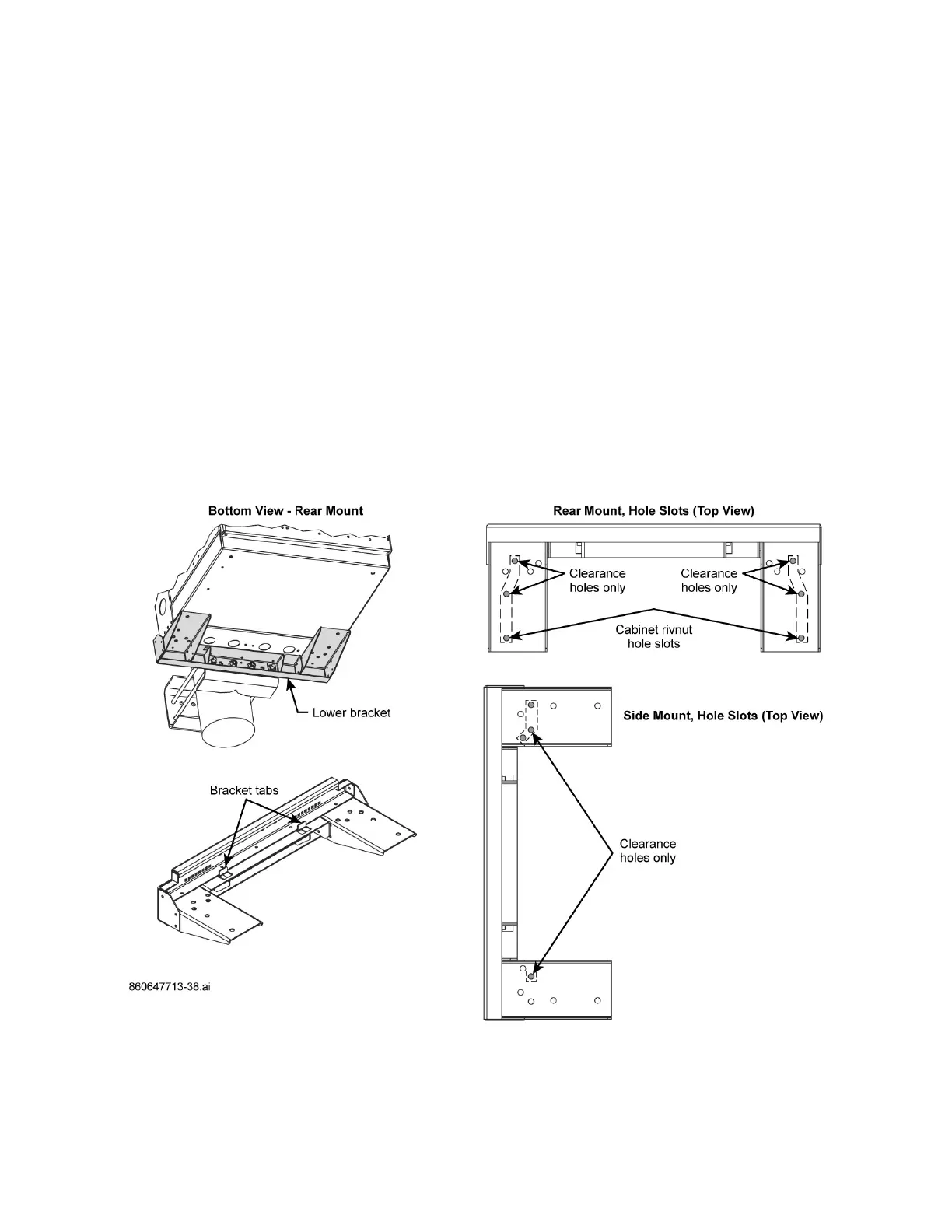
■ Cabinet Rear Mount
a. Verify cabinet rivnuts align with lower bracket holes to slot a 1.5 x 25 mm M10 screw through
each hole into rivnut per Figure 29. Fasten screws with lock and flat washers from kit to
rivnuts.
b. There will be two other clearance holes that align between lower bracket and cabinet floor.
Slot M10 screws through cabinet floor per Figure 29 and fasten M10 screws from inside
cabinet with a hex nut from kit. Hole pattern shown on Figure 29 matches Figure 40.
■ Cabinet Side Mount
a. Align lower bracket clearance holes to cabinet clearance holes (cabinet rivnuts do not align
with a side mount).
b. Slot M10 screws through cabinet floor per Figure 40 and fasten screws from inside cabinet
with a hex nut from kit.
5. Tighten M10 screws to fasten cabinet to the lower bracket.
Figure 40. Hole-Mount Usage, CMC-21/28 Rear and Side Mounting