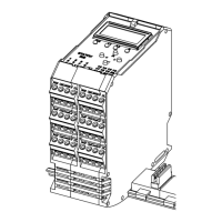
Statox 503 Control Module
Page 32 of 46 Issue 10 / 2018
Connecting the sensor heads
The sensor head power supply must be OFF before connecting a sensor head! Short circuits
on the terminals or selection of a wrong program may destroy the sensor head.
Following sensor heads can be operated in voltage mode:
Statox 501 HRC, ARE, LCIR, MCIR, CO
2
and PID for combustible gases, CO
2
and VOC.
Together with the two internal resistors of the Statox 503 module the sensor forms a Wheatstone
measurement bridge. A gas concentration-dependent resistor in the sensor leads to a change of the bridge
voltage. This voltage in the mV range is evaluated by the Control Module.
The standard application is 3 wire mode. Beginning with 750 m length of cable Compur recommends to
generally operate in the 5 wire mode. The two additional “sense” lines measure the sensor supply voltage
and compensate for voltage drops due to long cable or extreme temperatures.
Following sensor heads can be operated in current mode (4 - 20 mA transmitter):
Statox 501/S, Statox 501 Infratox, Statox 505, Statox 506 and Statox 560.
In transmitter mode the sensor signal is transferred directly to the analog output, according to the selected
program, with 4 mA as the lower end of the measuring range and 20 mA as the end of scale.
The sensor heads Statox 501/S and Statox 505/506 for toxic gases and oxygen are operated as 4 – 20 mA
transmitters in 2 wire mode. The Statox 505/506 sensor heads can be operated in 3 wire mode, too. This
way you can differentiate between service mode (2 mA) and system failure (0 mA).
The sensor head Statox 501 Infratox for combustible gases and CO
2
requires 3 or 4 wires for proper
operation.
The Statox 560 with self – test feature need 4 contacts.
The sensor heads Statox 501/S, Statox 505 and Statox 506 must be operated in connection with an
intrinsically safe repeater if they are installed in classified area, zone 1 or zone 2. Detailed information
regarding the operation with intrinsically safe repeater can be found in the manuals of the corresponding
sensor heads. Connect the shield of the sensor head cable to the grounding bar. Both, grounding bar and DIN
Rail must be grounded.