EasyManua.ls Logo

Compur Monitors Statox 503 - Page 33

Compur Monitors Statox 503
46 pages
Print Icon
To Next Page IconTo Next Page
To Previous Page IconTo Previous Page
Loading...
Statox 503 Control Module
Issue 10 / 2018 Page 33 of 46
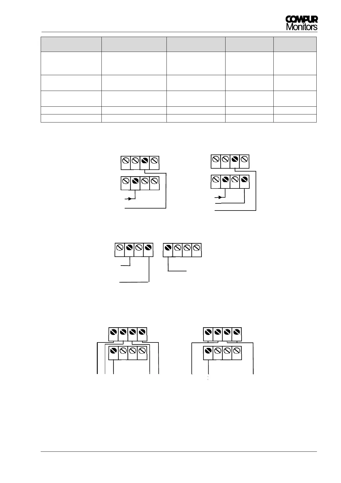
Sensor head type Signal Measuring mode Cable
Statox 501 HRC, ARE,
LCIR, MCIR, CO
2
,
Statox 501 PID
Voltage in mV:
non balanced bridge
Voltage mode 3 or 5
Figure 25
Statox 501/S
,
Current: 4 – 20 mA Current mode 2
Figure 23
Statox 505
Statox 506
Current: 4 – 20 mA Current mode 2 or 3
Figure 23
Statox 501 Infratox
Current:
4
20 mA
Current mode
3 or 4
*)
Figure 24
Statox 560
Current: 4
20 mA
Current mode
4
Figure 26
*)
one or two ground wires
5
6
7
8
9
10
11
12
5
6
7
8
9
10
11
12
3
3
1
2
5
4
5 o. 4
1 o. 2
2 wire mode
9
10
1
1
12
19 V
I
INP
5
6
7
8
9
10
1
1
12
I
INP
5
6
7
8
19 V
GND
3 wire mode Statox 505 / 506
Figure
23
:
Conne
ctions sensor heads Statox 501/S, Statox 505 and Statox 506
Figure
24
:
Conne
ctions sensor
head Statox 501 Infratox
5 wire mode
3 wire mode
Figure
25
:
Connections
sensor heads Statox 501 HRC, ARE, LCIR, MCIR, CO
2
and PID
9
10
11
12
I
INP
24 V
GND
21
22
23
24
2 Shunts come with each
Statox 501 sensor head.