UT-4500 Series C- and Ku-Band Up Converters MN/UT4500.IOM
Front and Rear Panel Connectors Revision 3
4–14
Item 8 – ‘P1 | RELAY’ Utility Connector
Use this D-Sub 9-pin female (DB-9F) connector to access the Form C Alarms
(relay closures). The mating connector is a DB-9M connector.
Table 4-5. ‘P1 | RELAY’ Pinout
1) Pin 1 to Pin 6: FAULT
2) Pin 2 to Pin 6 OK (NO FAULT)
3) Pin 7 to Pin 5: Forced Faults (typically used
with external group delay equalizers)
3
4
6 Summary Fault COM
Item 9 – Removable “Personality” Module
See Sect. 4.2.4 for information about these removable “personality”
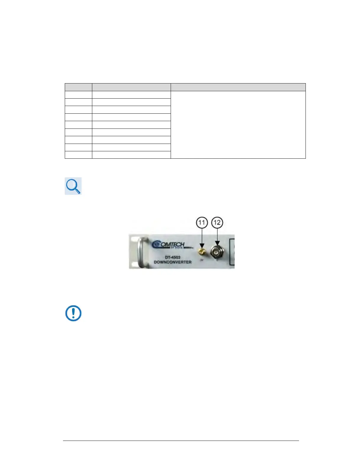
Item 11 – Front Panel RF Sample Test Point Connector
Figure 4-14. Front Panel Sample Test Point Connections
As shown in Figure 4-5 and Figure 4-14 (Item 11): This female Type ‘SMA’
connector (-20 dBc nominal) provides the user ‘RF’ test point interface.
An optional RF LO monitor (0 dBm nominal) is available in replace of
the RF Sample Test Point.
Item 12 – Front Panel IF Sample Test Point Connector
As shown in Figure 4-5 and Figure 4-14 (Item 12): This female BNC connector
(-20 dBc nominal) provides the user ‘IF’ test point interface.