UT-4500 Series C- and Ku-Band Up Converters MN/UT4500.IOM
Appendix A Revision 3
A–6
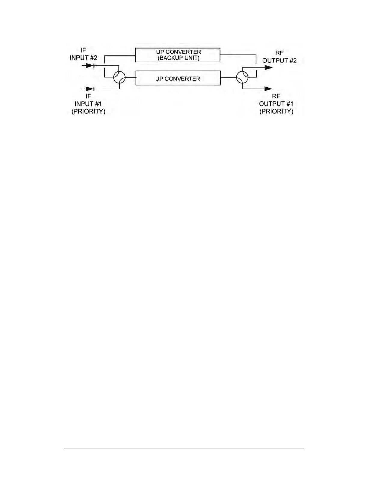
Figure A-6. 1:1 Redundant Configuration Diagram – Dual Source IF Input
(with IOM and TSM)
A.3.2 1:N Redundant Systems
IF and RF transfer switches in the TSM switch the IF input and RF output of a
faulted online converter to the BU. Figure A-7 shows the cable connections
between the converters. The IF input and RF output to the redundant converter
subsystem is connected to online converter ‘#N’. Figure A-8 shows the diagram
for this 1:N redundant "Daisy Chain" converter configuration.