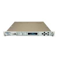
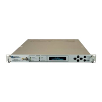
UT-4500 Series C- and Ku-Band Up Converters MN/UT4500.IOM / CD/UT4500.IOM
Table of Contents Revision 3
vi
2.2.9.6 IF Bandwidth ............................................................................... 2–10
2.2.10 Group Delay ....................................................................................... 2–10
2.2.10.1 Linear .......................................................................................... 2–10
2.2.10.2 Parabolic ..................................................................................... 2–10
2.2.10.3 Ripple .......................................................................................... 2–10
2.2.11 Phase Noise ........................................................................................ 2–11
2.2.11.1 UT-4505 ...................................................................................... 2–11
2.2.11.2 UT-4505/E, UT-4505/F, UT-4505/G, UT-4505/H, UT-4505/I,
UT-4505/J, UT-4505/K, UT-4505/M, UT-4505/N ....................... 2–11
2.2.11.3 UT-4514 ...................................................................................... 2–11
2.2.11.4 UT-4514/F, UT-4518, UT-4518/E ................................................ 2–11
CHAPTER 3. INSTALLATION AND STARTUP ................................... 3–1
3.1 Unpack and Inspect the Shipment ..................................................... 3–1
3.2 Install the Unit into a Rack Enclosure ................................................. 3–3
3.2.1 Install the Optional Rear Support Brackets Kit ..................................... 3–5
3.2.2 Install the Optional Rack Slide Set ....................................................... 3–7
3.3 Connect Prime Power Connection ..................................................... 3–8
3.4 Connect External Cables .................................................................... 3–8
CHAPTER 4. FRONT AND REAR PANEL CONNECTORS ................ 4–1
4.1 Overview – Cabling Connection Types ............................................... 4–1
4.1.1 Coaxial Cable Connections ................................................................... 4–2
4.1.1.1 Type ‘BNC’ .................................................................................... 4–3
4.1.1.2 Type ‘TNC’ .................................................................................... 4–3
4.1.1.3 Type ‘N’ ......................................................................................... 4–3
4.1.1.4 Type ‘F’ .......................................................................................... 4–3
4.1.1.5 Type ‘SMA’ .................................................................................... 4–4
4.1.2 D-Subminiature Cable Connections ..................................................... 4–4
4.1.3 RJ-45, RJ-48 Cable Connections ........................................................... 4–5
4.1.4 USB Cable Connections ........................................................................ 4–6
4.2 Unit Connectors ................................................................................ 4–7
4.2.1 Power Connections .............................................................................. 4–8
4.2.1.1 Power Interface Module – Standard AC Unit ............................... 4–8